Okay first thing is first you need to make sure you have the right type of screwdriver. I used a 0 so you can use the same. but the real size is a 00. Also the screws are torqued in and hard to turn at first. If you are using a 00 it shouldn't be too difficult. Or you Could just put your PSP on the bed and push down and try to unscrew it. Cyber has recommended Wrapping a screwdriver with tape too. Be careful not to strip the screws. I would recommend using a small pair of tweezers for this tear down too. And if you are wanting to be extra careful use a static wrist strap to ground yourself. You can get them at computer repair stores. Other than that remember that this is complex Computer circuitry. Do not touch any gold connectors, chips, or small pieces on the board directly. The only other thing I recommend is getting a notepad and writing down with labels which screws went where. Some people may be able to just remember.. The main outside screws all have this red coating on the outside so you can keep track of those. Except the black ones. Those look normal.
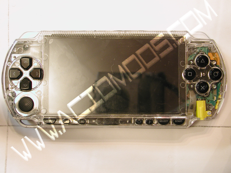
Okay as far as taking the PSP apart. There is an order I do it in and things I make sure of..
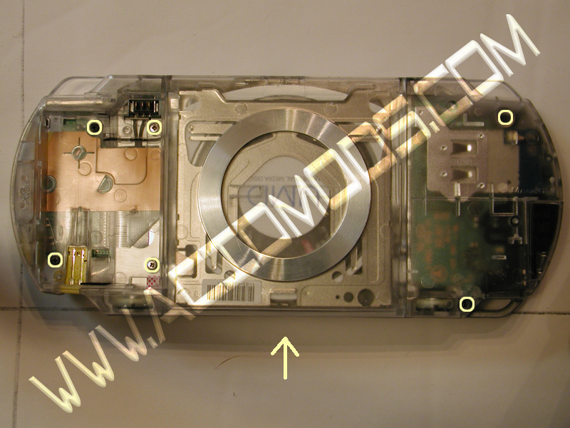
First thing there is to do is the black top faceplate and casing, If you are only switching out the faceplate and casing then you just unscrew what needs to be unscrewed and move over what needs to be moved. The Locations of the Screws are as shown…
Now to include the buttons, Stick, and nub. Take note of how the buttons are positioned in the case so you can place them back in the same way. Then place the rubber pieces over them and make sure you put it in right. the Stick itself is easy to figure out, you remove the nub, just pull it off the top. It's meant to come off. and then you unscrew the two screws that hold it down.
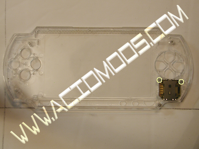
Here is what it should look like when you transfer it to the Clear case…. Remember that the sides of the case are at an angle. If you can't get it completely screwed down you are probably trying to put it straight on instead of at an angle. Once you are done with this then you just put it back on and make sure you snap it back at all the right places, then screw it down.
If you have to remove it all then I do it like this..
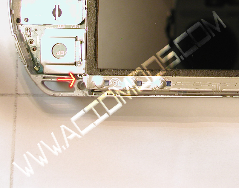
First is the home bar. It's attached by a little nub on the left side of the LCD case. You take a small flathead screwdriver and pry up just a bit on the bottom of that nub. The left side of it comes off and you can remove the Home Bar from the LCD. Here is the location of the Nub Point.
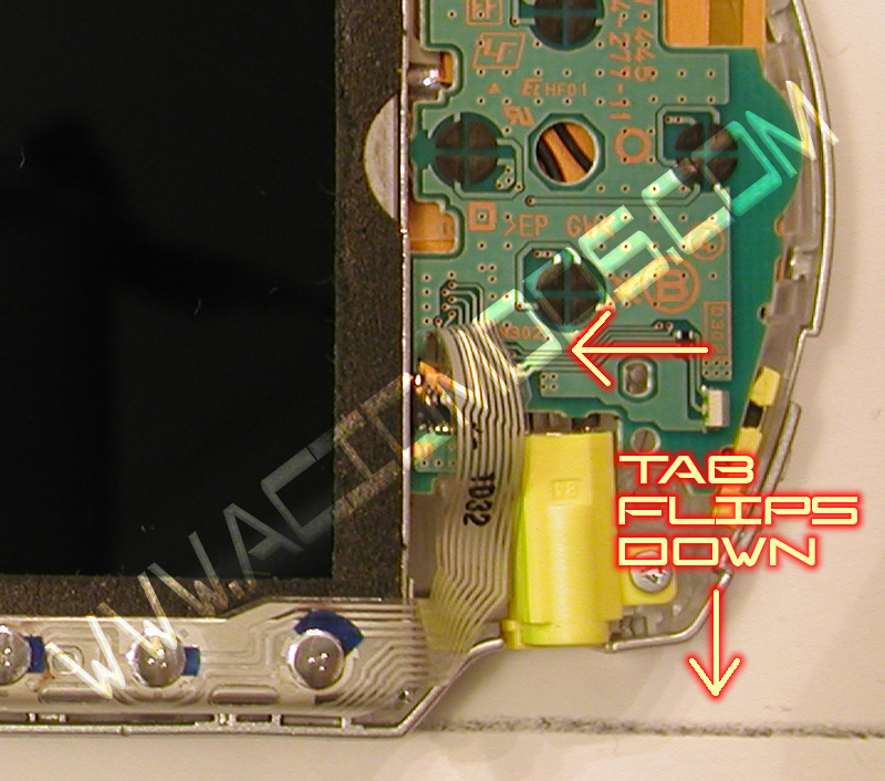
You have to remove the ribbon from the board. It is attached to the board by a lever system. In other words, there is a flap like tab that holds the ribbon in. You have to flip the tab up (very carefully) and then pull the ribbon out. If the ribbon isn't coming try flipping the tab further up. If the tab is up completely then the ribbon moves with ease. Sometimes unseating itself in the process. Here is the Location of the Ribbon Tab..
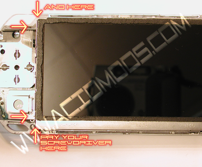
Once this is done you will need to remove the LCD from the LCD Cage, there are two latches on both sides of the LCD Case itself. They are under the case edge. If you pry a small flathead in between the screen and the LCD Case keep the screwdriver in there and put your finger under the LCD Screen and push up. It should come right out (BTW don't feel bad if you can't do this easily, It took me two hours to figure out this trick). Here are the Locations of the LCD Latches.. Just look at it and you will see them..
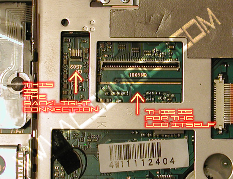
After you get the left side up, the right side is easy but don't pull the screen up too far. It is attached with two ribbons There is a tiny one at the left and a bigger one. Both are held down by the same lever system. A small tab that you flip up and remove the ribbons. The tiny lever is very delicate so use the utmost of care flipping it up. The biggest one is cake, just flip up the tab and remove. These two tabs are attached to the main board so do not try to remove any screws before you remove the LCD screen. I do not have a picture of this being done so I will show you where on the Mobo they are. The Small Tab flips Down, and the Bigger one Flips up…
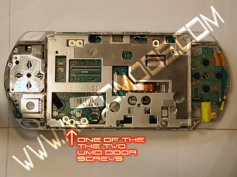
After you remove the LCD screen you will see the LCD cage under it. There are a number of screws you need to remove…. That will allow you to remove the LCD cage once you open the UMD door. The UMD door is held in partially by the LCD cage screw, so you should open the UMD door to remove the cage. It should be easy to take out but you may need to kinda pull it over to the right to remove the cage.
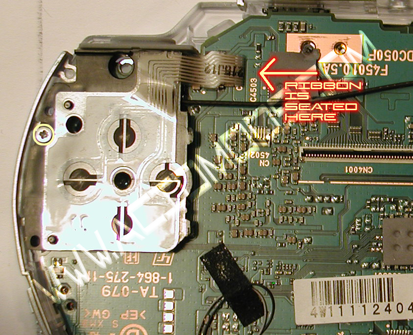
Under that is your motherboard and your Dpad and your ABXY Power board. You remove the screw holding your DPAD down, and then remove the ribbon the same as you have already.. Dpad Screw is Here…
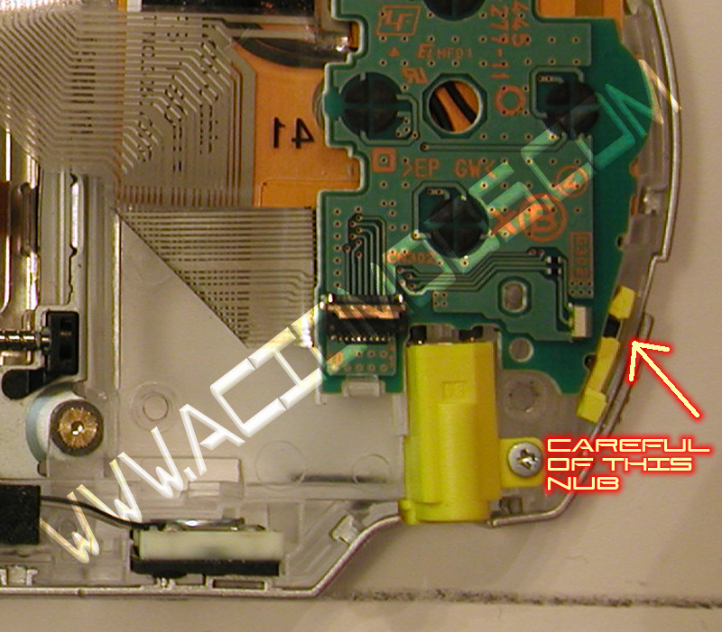
Then you remove the ABXY Power switch but carefully making sure that you get the little black nub out of the power switch on the outside. Note: when you remove that always take special care to know where that black nub is for the switch It's the easiest thing to break if you aren't careful When you reinstall the power board always make sure that nub is in the outer area of the switch correctly Before you push the board into place.

told me about how he took all day doing a huge LED mod and everything thing worked. Broke the switch off reinstalling it. Made the whole thing useless. I've broken the switch once. And I will not do it again.
Gently stick a small flathead screwdriver under it and slightly pull the screwdriver up and the board comes up rather easily. It has a Ribbon in the back attached to the back of the power switch and one on the Motherboard itself, both are tabbed with the levers. Flip the tab up and remove ribbon from the Motherboard and the ribbon from the power switch.
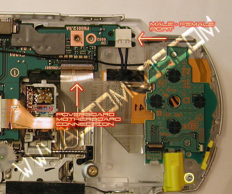
After the power board is off you can concentrate on some other things, like the AC adapter plug. you just carefully remove the Male plug from the female port on the motherboard. And then unscrew the yellow AC plug port and remove it..
There is also a Male Female port that holds the Motherboard into the Wireless card. (that's the long wire you see taped to the whole Motherboard). Note there are two other things that you would need to remove first. One is the two speakers. they are the white tiny plugs on the bottom of the Motherboard. They are easy to remove if you have a tiny set of tweezers. Once you remove these, you would want to use a small flathead screwdriver to pry up slightly on one side, and then use your tweezers to gently grab the speakers and pull them out of the case. They aren't soldered, so it's easy once you get one side up. Make sure you set these chips or components onto a surface that won't get Static electricity. like a table or
something.
The next thing you need to remove is the ribbon for the UMD Laser. This was a bit tricky to figure out because of the type of latch it is. There are two tabs on both sides of the ribbon, if you slide the tabs away from the port you release the pressure on the ribbon and it can be removed. You just slide one tab at a time to the right and it will eventually be released. You slide out those tabs a bit and the ribbon can be removed. It's still attached to the Laser mounting so ignore it for now. There is another ribbon for the other piece of the UMD Drive. It's at the very bottom of the Motherboard. Just flip up the tab and remove the ribbon.
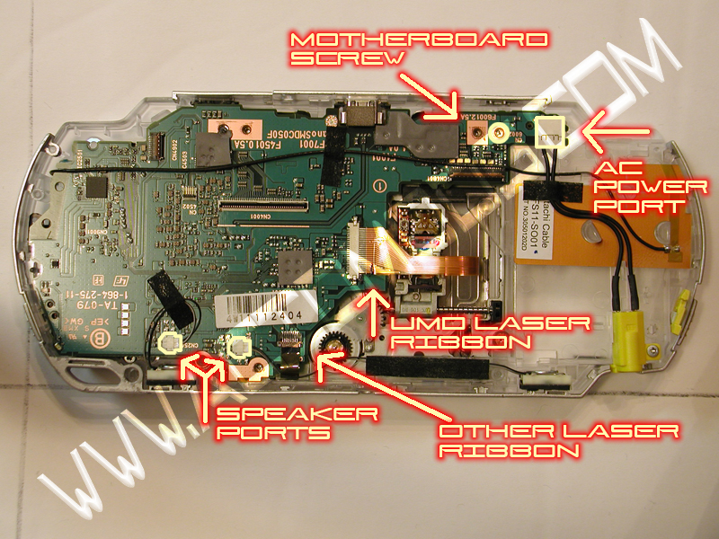
Now you need to remove the antennae from the right side of the psp. It's easy you just ease the antennae piece up from the black plastic and then disconnect the black tape that holds the cord down so you have free access to the motherboard. Here is a Rundown of everything you would be removing and where it is..
Now you can carefully remove the Motherboard by pulling up the top left hand side which detaches the male/female port that attaches the MEMcard reader and the bottom of the Motherboard. Then you carefully tilt the bottom of the Motherboard up so you can slide the USB port out of the top of the case and remove the motherboard. You will feel it disconnect. It doesn't take much force. It's like a plug kinda. It's just on the bottom of the motherboard. Now you should have the Motherboard out. The antennae will still be attached to the Wifi card and MEM stick reader. Just carefully set that down and then get to work on the small metal cage that covers it up.
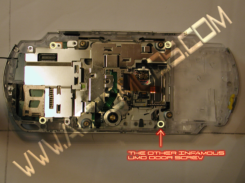
There are assorted screws that hold it down.
After you get it up you should notice that there is one small black screw to the right that doesn't seem to hold anything. It holds the UMD Door in place. Remove it. Now if you played your cards right you should be able to use a small exacto-knife from the back of the case with the UMD door open and place it at the base of the umd door inside and pry it carefully to the inside. Think *CD Case Backwards*. You know how the CD case holds in those little holes on the case to keep the case on it? Image that with the pegs backwards. that's how the door holds on. Once you get one side out you carefully wiggle out the other side and it will come right out.
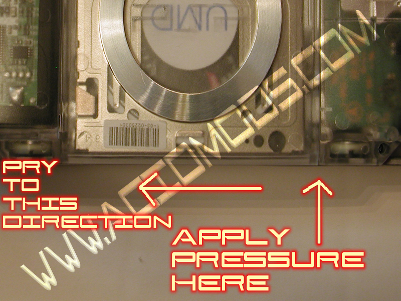
Here is a Diagram of where to do this. I used a butter knife..
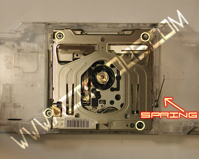
Now you need to remove the UMD Drive. It's the whole drive cage in the back. You remove four screws at each corner and it comes out. Then you need to remove that spring on the right side that puts the spring in the UMD opening. While you are doing that make careful note of how it is placed in there, cause you need to put it back in the same
way. Here is the Location of the screws and Spring..
After that is out you can remove the other things. There is a ribbon for your R button that is just attached by some adhesive. Just peel it off then attach it to the new case by restricting it like a sticker. Be careful not to touch the bottom connectors though. the gold part.
Not everything is removed yet but you are doing great!
Now you can see the Wificard on the left bottom area. There are like two screws holding it down and then you have to keep in mind that the Headphone Jack plugs into the bottom of the case so pull that port out of the case with a tipping up motion and you should have the Wifi card easily come out.
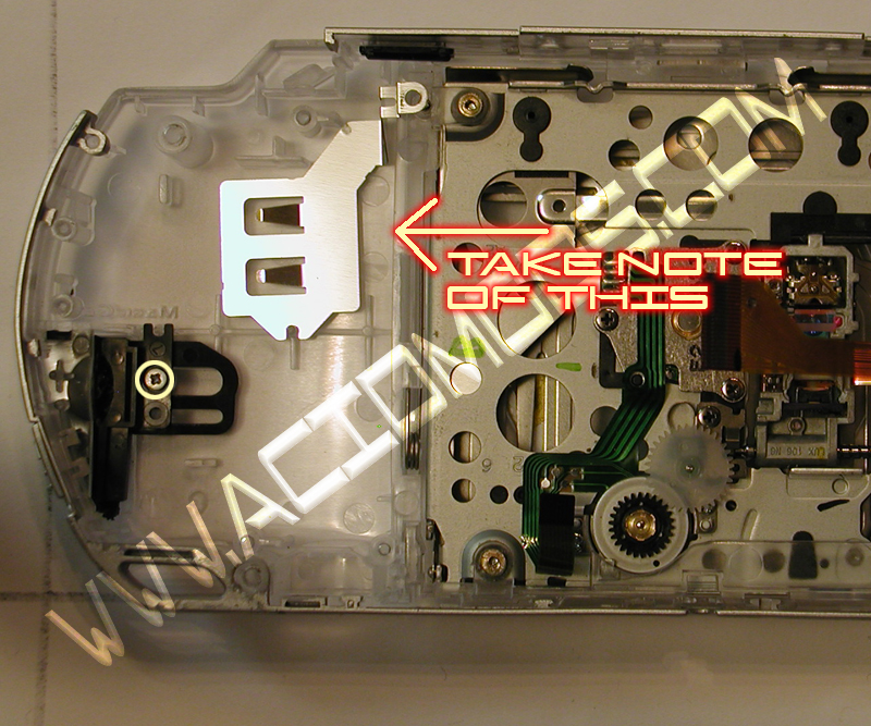
Now there is a small metal piece below it that you can just take out. And your PSP is down to the MEM Stick Door and the power switch.
(Although if you want to trade the grey frames there is a bit more work)
For the MEM stick door you need to remove the screws holding it down and take off the top piece. Make sure to note how it is put in there…
Once it is loose you remove the mem stick door from the PSP. Now you have to get the Rubber piece off of it so you can install it into your new case. You need a small pair of computer pliers and an exacto knife. The rubbery plastic will separate from the black mem stick door, There are five small black pins holding it on. If you look at the clear one (Coolmods) you will see those pins, The Sony Black OEM case has larger ends on the
end of the pins and they look like little mounds but don't be fooled. You will need to slice through the ends of those pins to remove the Rubber. (If you look at the Coolmods one, you will see the pins. just use those as reference to find the rounded ends). The ends of the pins are slightly larger than the pin itself so it can hold the rubbery plastic in place. Just be patient and you will get it off. (I broke a pin off my original one figuring this out.. lol).
Now the power switch. The power switch is made of two parts. One part is like a hook thing on the switch part. And that goes through a hole on the yellow part that triggers the switch. You take a small screwdriver and push down the grey part that goes through the yellow trigger and the grey switch will come out. It's not rocket surgery. The yellow piece just comes out (I'm not sure if this is the same for All PSP Models. My PSP was a newer model and this may be different for earlier models). Your PSP should be bare now aside from the stock frames.
Be sure you note that the clear case isn't going to fit like a glove. You may need to use more force to get some things to fit but be careful. If you find it won't fit, try sanding the open port on the case to try and make a better fit. ( Had a particularly interesting time with my Wifi Card Fitting right.. I got it in there eventually though.
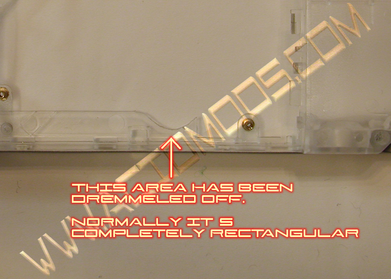
One thing that many Acidmodders have been talking about is the UMD Drive Gears stopping the PSP from loading UMDs. If this doesn't happen then don't worry about it. If you can hear the UMD gears turning, then you have this problem. The easiest way to solve this is to dremel off the plastic piece that covers up the UMD Gears. but you risk getting you speaker wires. The best way I found to solve this is to take a Dremel with a round head and just round out whichever side of the round area on the bottom of the plastic piece doesn't get enough clearance to let the gear move. (If you don't have a dremel, then a sharp knife should do.. Just be careful and take little bits at a time.) Just look at your Clear case and where the gears go and I'm sure you will see that they would get slowed down. Use your best judgment and take little bits at a time till you get it right! (T3KN1K4L’s PSP is heavily Dremeled but it kept it’s shape enough.
Also be wary of the Speaker wire from right speaker. They can get caught in the gears and slow it down too. Just check the back of the LCD Cage for that rubber spacer. It's used to prevent such an occurrence. Make sure that the wires are below that and you will be fine!
(for some reason while your case is open it works. Once you screw it down is when this occurs)
If Coolmods has fixed this problem with the new cases.. Then never mind.
Once your case is stripped you have some options.. Some coolmods cases come with frames (the outer grey part with the switches). Some do not. If you like the look of your original frames then I included how to remove them in this Tut.
You will see little tabs on the inside of the frames that hold the frame on the case itself. This is depicted in my pics. First you need to remove the switches. You already got one of them off! Good for you!
The second is the Wifi Switch. It's basic. just see how it goes in there. Pretty much the same as the power switch, and remove it. then you can use
the tabs to slowly slide the frame off towards the top of the case. It comes off with a little pressure but don't use too much. They are fragile. The side frame will come off with ease too. It's the top that's the ticker.
If you got your IR Sensor off with ease then good for you! Sometimes it just pops out! (I know mine didn't) If you didn't then just apply some slight pressure with a small flathead screwdriver to the back of the IR Sensor and it will pop out. The open button is just wedged into the frame. Just pull it out at an angle and it will come out rather easily.
Then you just carefully, slide the frame towards you. You will notice that it stops and if you look at it you will see. two little tabs on both sides of the top frame that hold it on. Pull the tabs out of the slots and slide it back toward you. It should come off.
Now you replay this all in reverse! Okay, now that everything is all taken apart I wanted to voice out something that anyone should watch for.. There is a tiny black tab on the back of the Motherboard that is depressed when the UMD door is shut with a UMD in it. This is very delicate and goes through a small opening in the in back of the UMD Laser Assembly that lets this tiny nub through so it can get pressed by the UMD Disk. Take extra care to make sure that tab goes into the UMD Laser Assembly correctly, If you break it off. (And it is easy to do) Then your UMD Drive won't turn on. For best results I recommend using this Tut with the new Virtual PSP Modder. Make sure to take care of your screws and remember where they all go! This shouldn't give you too many problems. If you find that you can't use all the screws, just use the ones you can and make sure everything is screwed down as best as possible. You don't have to use all of them. Just as many as you can.
Thanks to Poseidon04 for his help on the Mem stick door (god I hated that thing)
And thanks to Acidmods for giving me the chance to help others like me!
Thanks to CyberPyrot for starting
www.Acidmods.comIf you have any problems don't hesitate to join us on the AcidMods forum and ask.
This tutorial is only for use at Acidmods.com, if you see this anywhere else. Knock them in the side of the head