Here is the tutorial.
To do this mod you will need:
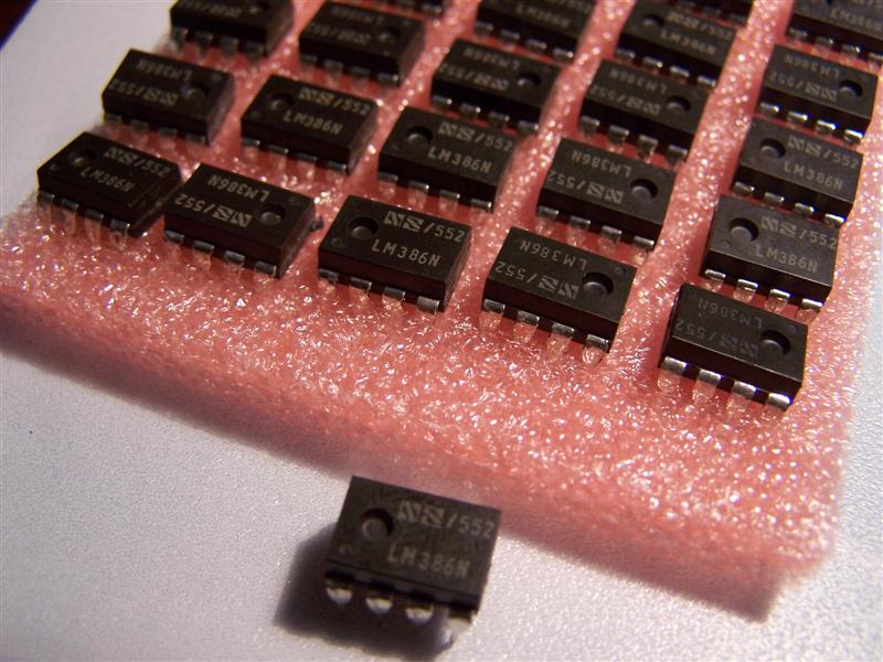
a sound amp chip, part number: lm386n
tri-wing screw driver
wire
LEDs
solder
The sound mod chips I got looked like this:
The wiring diagram looks like this:
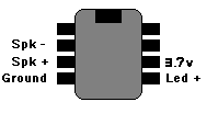
it is the same as the psp, but the DS lites battery only has 3.7v
To get the 3.7volts to power I connected it right up to the battery, if you want you could put a switch in there so no power goes to the chip when the system is not on. To get the power you can just solder it right before the fuse coming off the battery on the ds, its labeled “F2”.
To get the ground or negative you can just connect it to any negative on the board, so I just used this spot in this picture:
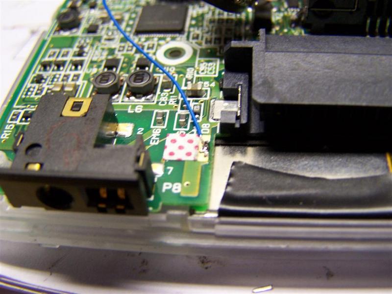
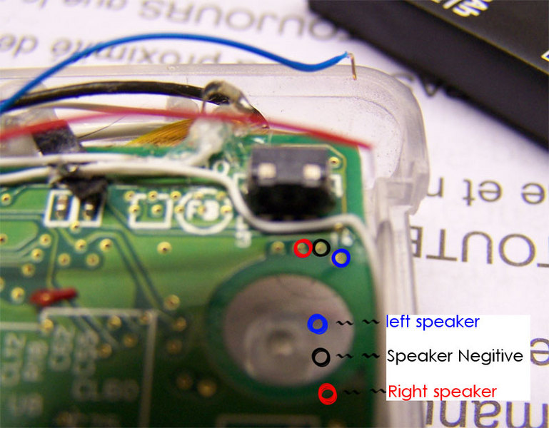
for sound positive and negative you can either connect it to the speakers (but thats a lot of work because you have to go up to the top section of your ds) or you can connect it to the holes coming off the ribbon in this picture.
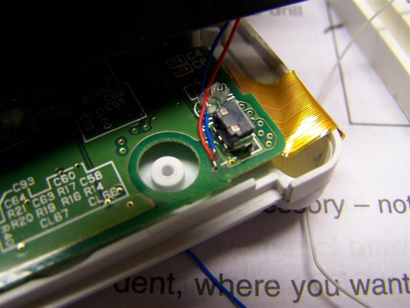
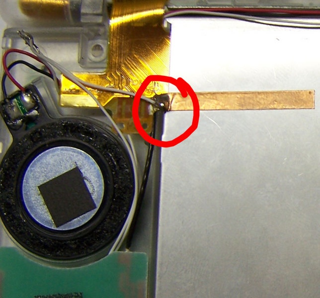
Then just connect the led positive to the bottom right pin on the chip and connect negative either to the negative on the chip or negative on the board, or if you want on the top section of the ds you will see a ball of solder next to the screen on the ribbon, you can just solder your negative of your led to that.
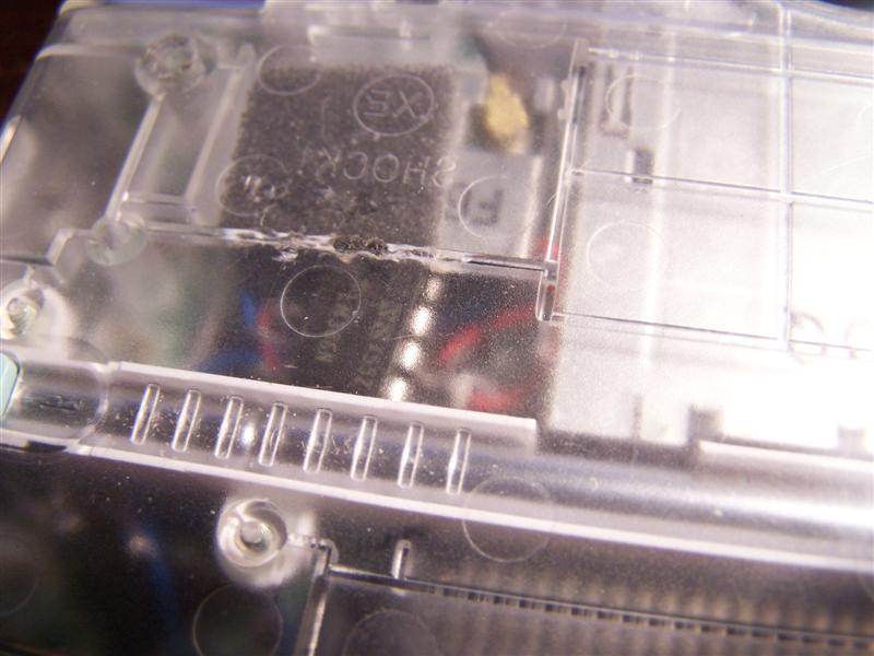
Then to make your chip fit you may have to cut a little hole in the plastic just above the stylus slot.
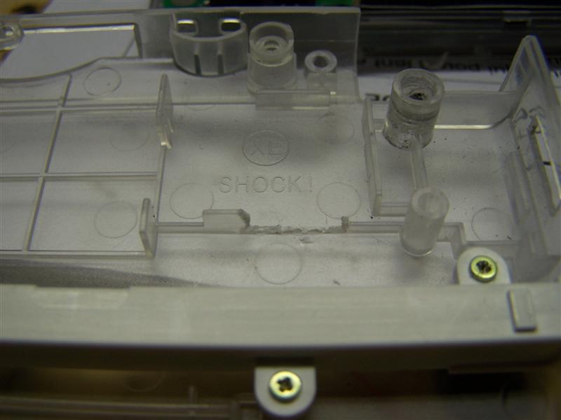
Then to be safe put some electrical tape down right below your chip and if you want you can glue it down. You can run all your wires under the ds slot rather than going around it. Then put it back together and test it.
If a admin wants to move this to the wiki please do as I cant.