Author Topic: XB1 Controller PCB Scans, Traces and Info - 1537  (Read 322247 times)

Offline rubs

  • Guppy
  • *
  • Posts: 7
  • Post quality +0/-0
  • Acidmods User
Re: XB1 Controller PCB Scans, Traces and Info - 1537
« Reply #390 on: November 09, 2023, 02:59:36 PM »
Hi Raph. You're right, the 1537 model doesn't have Bluetooth. I've taken it apart, and I'm trying to compare the voltages with a known working board. It seems someone already tried to replace the U3B board, but I think it's not an easy job, so I don't know if they succeeded. Sorry if the text is confusing. I don't know how to punctuate in English.

Offline Raph

  • Chief squatting Hard
  • *
  • Posts: 15
  • Post quality +0/-0
  • Gender: Male
  • Acidmods User
Re: XB1 Controller PCB Scans, Traces and Info - 1537
« Reply #391 on: November 09, 2023, 11:33:50 PM »
Hi Rubs, it's actually a good idea to compare the voltages with a comparison card that works.
At the moment I only have one 1537 controller so I can't compare the voltages of the controller I'm trying to repair.

I don't see what you mean by U3B board are you talking about USB or is it a part that I don't know? Have you tried connecting it to your Xbox then going into the application to manage Xbox accessories to update the controller's internal software? Maybe this could solve the connection problem.

No problem with punctuation, for my part I am French and I use Google translate to be sure that I am understood and then I reread to remove the odd turns of phrase due to automatic translation.

Have a nice day !
« Last Edit: November 09, 2023, 11:35:11 PM by Raph »

Offline Raph

  • Chief squatting Hard
  • *
  • Posts: 15
  • Post quality +0/-0
  • Gender: Male
  • Acidmods User
Re: XB1 Controller PCB Scans, Traces and Info - 1537
« Reply #392 on: November 11, 2023, 09:49:55 AM »
Hi RDC et ZhenyaKa, I tried the solutions you gave me, I tested by putting paper clips (because my tweezers were too big) so a paper clip with the two parts put in the bottom holes of rb and a another paper clip with the two parts in the two holes at the top of rb. When with my multimeter I test if the paper clips conduct the electricity, that works. If I put my multimeter with a tip on each paperclip, the electrcity does not flow, I do not know if it is normal. I think the problem comes from the power supply of the rb button. What do you think?

Offline RDC

  • Administrator
  • Around the block
  • *
  • Posts: 2611
  • Post quality +90/-2
  • Gender: Male
  • The CGnome Project
Re: XB1 Controller PCB Scans, Traces and Info - 1537
« Reply #393 on: November 11, 2023, 11:09:17 AM »
Post a picture of your board.
Screwing up is one of the best learning tools, so long as the only thing you're not learning is how to screw up.

Offline Raph

  • Chief squatting Hard
  • *
  • Posts: 15
  • Post quality +0/-0
  • Gender: Male
  • Acidmods User
Re: XB1 Controller PCB Scans, Traces and Info - 1537
« Reply #394 on: November 13, 2023, 05:41:07 AM »
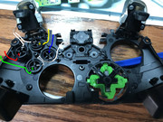
Hi, sorry for my late response, here are the photos of both sides of each card so you can see if there is a problem. As you can see the second card is in perfect condition. I did a lot of soldering because I thought the buttons I had were broken. I also scratched the green protection of the PCB to see the state of the copper underneath. Please be lenient as this is my first controller repair.  :victory:

Offline Raph

  • Chief squatting Hard
  • *
  • Posts: 15
  • Post quality +0/-0
  • Gender: Male
  • Acidmods User
Re: XB1 Controller PCB Scans, Traces and Info - 1537
« Reply #395 on: November 13, 2023, 06:07:43 AM »


Offline RDC

  • Administrator
  • Around the block
  • *
  • Posts: 2611
  • Post quality +90/-2
  • Gender: Male
  • The CGnome Project
Re: XB1 Controller PCB Scans, Traces and Info - 1537
« Reply #396 on: November 13, 2023, 06:25:50 AM »
Put a new switch in there, solder up the 3 that are still there, if they will take solder, if not all of them are ground. Then solder the last pin of it with a jumper wire to J2p5, taking care to route the wire where the shell will not pinch it.

« Last Edit: November 14, 2023, 10:32:10 AM by RDC »
Screwing up is one of the best learning tools, so long as the only thing you're not learning is how to screw up.

Offline Raph

  • Chief squatting Hard
  • *
  • Posts: 15
  • Post quality +0/-0
  • Gender: Male
  • Acidmods User
Re: XB1 Controller PCB Scans, Traces and Info - 1537
« Reply #397 on: November 13, 2023, 06:35:53 AM »
Thank you for your answer, so I have to put a new rb button, I solder the three pins and I leave the one circled in purple without soldering, then I solder the last one and I connect the solder to the bottom connector of the PCB which is colored in purple?

Offline Raph

  • Chief squatting Hard
  • *
  • Posts: 15
  • Post quality +0/-0
  • Gender: Male
  • Acidmods User
Re: XB1 Controller PCB Scans, Traces and Info - 1537
« Reply #398 on: November 14, 2023, 08:53:45 AM »
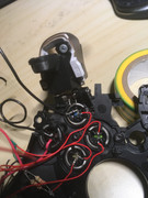
Hi, here are the photos of my repair, however the rb button still does not work, I will let you look so you can tell me if you have an idea why it does not work.


« Last Edit: November 14, 2023, 08:55:26 AM by Raph »

Offline RDC

  • Administrator
  • Around the block
  • *
  • Posts: 2611
  • Post quality +90/-2
  • Gender: Male
  • The CGnome Project
Re: XB1 Controller PCB Scans, Traces and Info - 1537
« Reply #399 on: November 14, 2023, 10:34:21 AM »
That looks more like you used solder instead of wire, and if it's connected at J2 there I'd be surprised. Make sure the ground side of the RB buttons is still connected to ground also.
Screwing up is one of the best learning tools, so long as the only thing you're not learning is how to screw up.

Offline Raph

  • Chief squatting Hard
  • *
  • Posts: 15
  • Post quality +0/-0
  • Gender: Male
  • Acidmods User
Re: XB1 Controller PCB Scans, Traces and Info - 1537
« Reply #400 on: November 14, 2023, 01:15:15 PM »
Thank you for your answer, I am sorry if I am not very good, I am trying to do that as best as possible. So I will try again tomorrow with copper wire instead of solder, and I will check the rb solders at the motherboard. do you think the copper could melt with the soldering iron?

Offline RDC

  • Administrator
  • Around the block
  • *
  • Posts: 2611
  • Post quality +90/-2
  • Gender: Male
  • The CGnome Project
Re: XB1 Controller PCB Scans, Traces and Info - 1537
« Reply #401 on: November 14, 2023, 02:02:59 PM »
No need to apologize for not getting it right the first time. If your soldering iron can melt copper, which takes ~2k degrees F (just over 1k C) then you have far bigger issues. ;)

Now lifting traces off the board after soldering to it, that's a different thing completely, and it means you are leaving the heat on there for far too long. Even though it's really thin copper, it's not melting it, it's just causing it to 'unglue' from the board and come off. The solder has melted, stuck and done it's job long before it gets to that point, as solder only takes 200~800F (90~450C) depending on the type used.
Screwing up is one of the best learning tools, so long as the only thing you're not learning is how to screw up.

Offline Raph

  • Chief squatting Hard
  • *
  • Posts: 15
  • Post quality +0/-0
  • Gender: Male
  • Acidmods User
Re: XB1 Controller PCB Scans, Traces and Info - 1537
« Reply #402 on: November 15, 2023, 10:17:41 AM »
Hi, it still does not work, this time I used copper wire that I soldered. I redid the other soldering of the rb button but it does not change anything. Is there something I did wrong or is the problem coming from somewhere else ?   :wacko:


« Last Edit: November 15, 2023, 10:18:13 AM by Raph »

Offline RDC

  • Administrator
  • Around the block
  • *
  • Posts: 2611
  • Post quality +90/-2
  • Gender: Male
  • The CGnome Project
Re: XB1 Controller PCB Scans, Traces and Info - 1537
« Reply #403 on: November 15, 2023, 10:29:28 AM »
That wire is way, way too large for that kind of repair, and honestly that looks worse than the solder did before. Given how the soldering is splashed all over at J2, I can't believe it doesn't have any other issues now.

It's still not past the point of being repaired, but if you keep going in that direction it's going to get harder and harder.

Remove that wire and clean all of that up with some rubbing alcohol and Q-tips and lets start over.

What are you using for a soldering iron and solder there? Do you have a DMM? Digital Multi-Meter
Screwing up is one of the best learning tools, so long as the only thing you're not learning is how to screw up.

Offline Raph

  • Chief squatting Hard
  • *
  • Posts: 15
  • Post quality +0/-0
  • Gender: Male
  • Acidmods User
Re: XB1 Controller PCB Scans, Traces and Info - 1537
« Reply #404 on: November 16, 2023, 07:41:35 AM »
Hi, thank you for your reply. I will do the soldering again because it is true that it is not great. I have an 80 watt soldering iron (maybe a little too powerful), it tends to burn my solder instead of melting it. I feel like I am welding with Superman's eyes ! I use 100% tin solder. I actually have a digital multimeter. I will send you a photo later in private of my equipment to get your opinion.

Offline RDC

  • Administrator
  • Around the block
  • *
  • Posts: 2611
  • Post quality +90/-2
  • Gender: Male
  • The CGnome Project
Re: XB1 Controller PCB Scans, Traces and Info - 1537
« Reply #405 on: November 16, 2023, 09:00:30 AM »
If you're using 100% tin and no really good flux that would explain a lot. Get yourself some 60/40 or something around that ratio (Tin/Lead) rosin core solder.
Screwing up is one of the best learning tools, so long as the only thing you're not learning is how to screw up.

Offline Raph

  • Chief squatting Hard
  • *
  • Posts: 15
  • Post quality +0/-0
  • Gender: Male
  • Acidmods User
Re: XB1 Controller PCB Scans, Traces and Info - 1537
« Reply #406 on: November 16, 2023, 10:04:54 AM »
OK thanks I will look for that. This might explain why I have trouble soldering.

Offline sekto

  • Guppy
  • *
  • Posts: 1
  • Post quality +0/-0
  • Gender: Male
  • Acidmods User
Re: XB1 Controller PCB Scans, Traces and Info - 1537
« Reply #407 on: February 20, 2024, 06:03:30 PM »
Hi guys. I really don't know if I'm posting this on the correct place.
I have a really old controller board that I thought it wasn't working anymore. But when I plugged, voil?, it was working but with the problem of start keep being pressed. When I was trying to fix, I broke a coil on L4 and I cant find any PCB to discover the value of this piece. I tried some different, from other boards, and sometimes it turn on, others it just heats.

Can someone tell me the value of this coil (any image) or can I make another circuit?


L4 with a random coil:


Board:


Board (another coil is close to leave me  :beg: )


CloseUp

Offline RDC

  • Administrator
  • Around the block
  • *
  • Posts: 2611
  • Post quality +90/-2
  • Gender: Male
  • The CGnome Project
Re: XB1 Controller PCB Scans, Traces and Info - 1537
« Reply #408 on: February 21, 2024, 01:56:39 PM »
Schematic for that board is on the first page of this thread. L3 and L4 on that board are the same value also.
Screwing up is one of the best learning tools, so long as the only thing you're not learning is how to screw up.

Offline rubs

  • Guppy
  • *
  • Posts: 7
  • Post quality +0/-0
  • Acidmods User
Re: XB1 Controller PCB Scans, Traces and Info - 1537
« Reply #409 on: April 08, 2024, 04:14:02 PM »
Hi guys. I have a controller working fine on USB but it doesn't turn on using batteries (it just flashes 1 time). The top power board is working just fine, I've tested it using another bottom MCU board and everything went ok (using both USB and batteries).

Any suggestion?

Offline RDC

  • Administrator
  • Around the block
  • *
  • Posts: 2611
  • Post quality +90/-2
  • Gender: Male
  • The CGnome Project
Re: XB1 Controller PCB Scans, Traces and Info - 1537
« Reply #410 on: April 08, 2024, 05:45:00 PM »
Don't think I've run across that before. Typically the top board having an issue with L1 or a broken trace will cause that exact issue, but for the bottom board to cause it, it would have to be a bad trace, via, solder connection at the MCU or the MCU itself.

See if the FW will update over USB and if that does anything. I'd suspect not, and then I'd look at the bottom board trace from J5p11 to U1p83 to see if it was open. That's like the 'Power OK' signal from the MCU that keeps the top board powered up so the bottom board will work. If that signal isn't there, you only get power when the Guide button is held down. An issue with D26, Q8 or Q9 and really anything in that circuit there will also cause that issue, but again those are all top board problems and just that Power OK line is all I can think of right now, well that or a bad MCU, that would cause that issue if everything on the top board is good.
Screwing up is one of the best learning tools, so long as the only thing you're not learning is how to screw up.

Offline rubs

  • Guppy
  • *
  • Posts: 7
  • Post quality +0/-0
  • Acidmods User
Re: XB1 Controller PCB Scans, Traces and Info - 1537
« Reply #411 on: April 09, 2024, 07:57:39 PM »
Thank you, RDC!

You nailed it. There was power only when holding the Guide button down, so following the path from J5p11 to U1p83 I found some broken traces.

After repairing those traces the controller was 100% fixed.

Here are some images.

Broken traces:


Soldering wires to repair the traces:


Conformal coating


Offline RDC

  • Administrator
  • Around the block
  • *
  • Posts: 2611
  • Post quality +90/-2
  • Gender: Male
  • The CGnome Project
Re: XB1 Controller PCB Scans, Traces and Info - 1537
« Reply #412 on: April 10, 2024, 01:29:48 PM »
Welcome, not my first rodeo. ;)
Screwing up is one of the best learning tools, so long as the only thing you're not learning is how to screw up.


SMF spam blocked by CleanTalk
SimplePortal 2.3.5 © 2008-2012, SimplePortal