I can't recall if I ever posted this around here or not, just found the draft for it in my PS3 folder and it's around 3 years old, but it was about installing this thing. You might find some of it useful also...
----------------------------------------------------------------------------------------------------------------------------
This was thought up and done by Hazer here on the AM forums, so all credit goes to him for it. I have nothing to do with it besides the way I went about installing it here is all. His entire post should be read thru before thinking of attempting this, as well as the place to grab the files you'll need for it if you decide too. Some of it is gone over again here, but either way it should be read thru first. -
https://www.acidmods.com/forum/index.php/topic,39591.0.htmlThis isn't exactly a full 100% step by step install tutorial, but it's more than a just how I did it thread as well.
I wanted to keep all of the wiring on the back side of the controller board, so this is a tad more difficult, on top of how much it already is, than it could be. After all of the prep work is done, then the board can be reinstalled with no having to flip it back or wiring on the top side that could come loose and it all pulled apart for a repair.
This was installed on a VX5 version PS3 controller, though the pictures can apply to the VX4 as well, since that board is pretty much in the same layout, but it should be double checked if anyone attempts it. The version of controller doesn't matter, since all of the PS3 controllers work the same way, it's just the spots everything would go will be different depending.
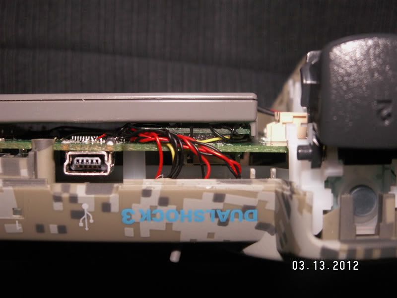
Decide if you're going to use the USB connector of the controller for the Programming cable, or an external USB connector of some sort. Either way will work, but if you use the controller's USB connector then you need to cut 2 more traces and use a DPDT switch for the install. I used the USB connector and a DPDT, the one Hazer did was with a 2.5mm headset jack, again either way will work the same, this is just how I did this one.
Tools
Programmer that can flash a PIC 18F14k50
Hex files for the PIC
Phillips screwdriver
Soldering Iron
Hot Glue Gun
Xacto knife
Parts
PIC 18F14k50
12MHz Xtal
Tact switch, N.O. Momentary type (For Programming button)
Resistors
- 100ohm x1
- 10k x 3
- 13k x 2
- 14k x 2 (just in case)
- 22k x 2
- 86k x 1
Capacitors
- 0.1uF x 1
- 0.47uF x 1
- 18pf x 2 (For Xtal. Optional but recommended. Check the Xtal DataSheet for the recommended value)
DPDT switch (only if USB connector is going to be used)
Connector for USB Programming Cable. (only if USB connector is NOT going to be used)
LED - BiColor, Red/Green. Do not use an LED that has 3 leads as it has either a Common Anode or Common Cathode connection made internally, and that will not work for this. You can use either 2 separate LEDs, or some SMT version that has them both in the same package, but still gives you access to each LEDs connections separately.
NOTE - This isn't an easy modification and it has it's challenges, plus the PS3 controllers aren't as forgiving as most other controller's circuit boards. Even if you're the cat's arse with the 360 controller, the PS3 controllers are a completely different animal. Don't find out the hard way you shouldn't have tried it, or you'll at best end up with a ruined controller. If you have money to throw away on ruined controllers, then just have someone that can do it build the thing for you so everyone comes out ahead.
This assumes you have the controller already taken apart and the board removed, because if you need help with that part of it, then the rest of this is something that shouldn't even be thought about attempting.
First desolder the Left Stick from the board, 16 solder joints. Cut the trace where the Black mark is. This is ideally the maximum area the Xacto blade should touch. A new blade in the Xacto knife will make a world of difference here. This is also the easiest trace to cut for this mod.
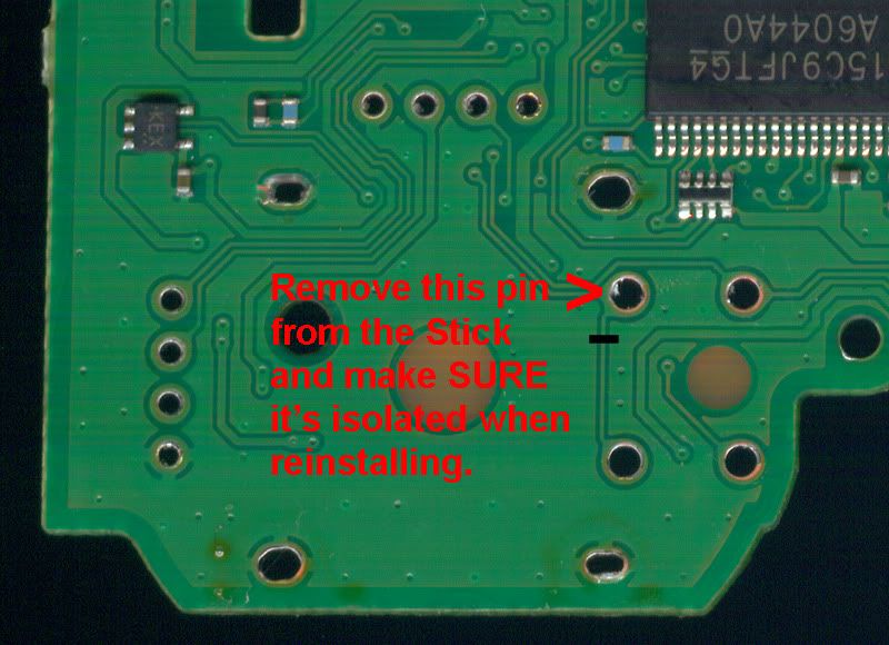
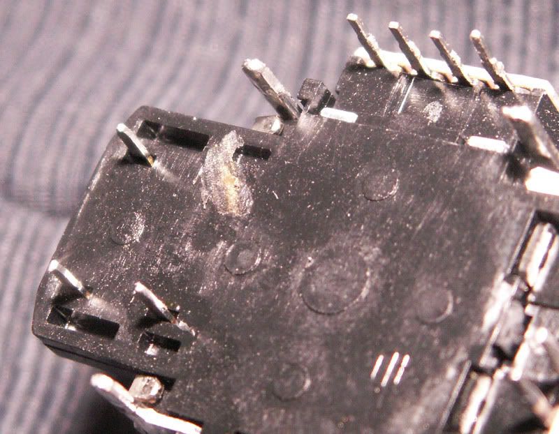
Then take the Stick and cut the marked pin. Either use a small piece of tape or cut the pin flush, or more, with the plastic of the Stick so it's isolated from the hole it was originally in. After that trace has been cut and the pin removed you can reinstall the Stick.
There are 3 traces on the back side of the board that need to be cut. Again, be VERY careful when cutting them as other traces around them don't want to be cut. Use a good magnifying glass and more than adequate light so you can see what you're doing. Again the traces need to be cut are where the Black marks are.
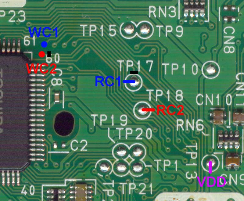
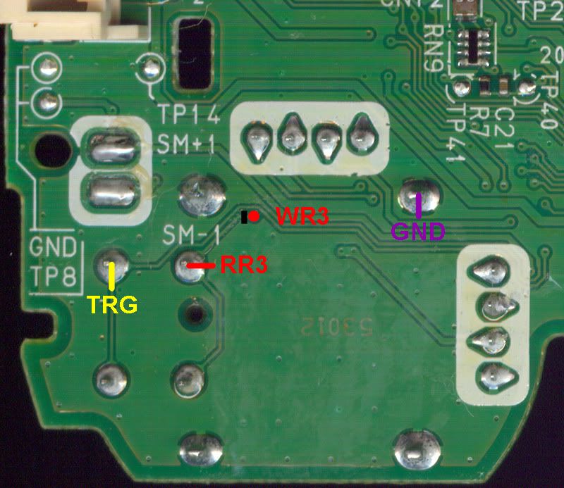
If you are going to use the USB connector, then there are 2 more traces that need to be cut.
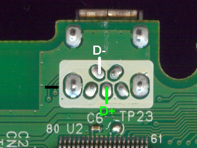
At this point you should install the LED, Programming button and if you're using the USB connector then install the DPDT switch. If not, then install whatever connector you're using for the Programmming cable.
The wiring for the DPDT switch is the USB connector goes to the 2 middle pins of the switch. Then one side of the switch goes to the controller's TP2 (D-) and TP3 (D+) spots on the board, while the other side will go to the D- and D+ connections of the 18F14k50 chip. Make SURE that all of the D- and D+ connections are wired correctly. If you get a D- and a D+ crossed it's not going to kill anything, but it's not going to work either.
The Programming button, LED and DPDT/connector can be installed wherever you like, as long as there is room. This is just how I did this one.
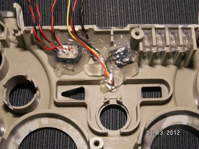
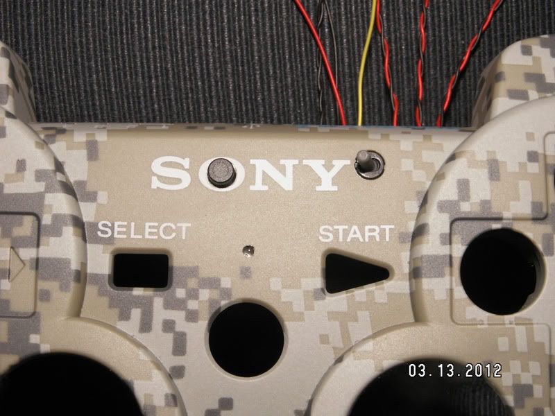
The PIC 18F14k50
Use the programmer and flash the USB Device BootLoader.hex file to the PIC.
After that has been done, you can use the BootLoader.exe to flash the Remap Project.hex file to the PIC. Make sure the Xtal is installed on the PIC at this point, or it will not run and thus the BootLoader.exe app will not see it.
Once you have the PIC flashed and then programmed, you can build the circuit up however you like. I opted to have a board made so I could keep the components small, and it's easier in the long run to deal with, but any method will work the same as long as everything is connected correctly.
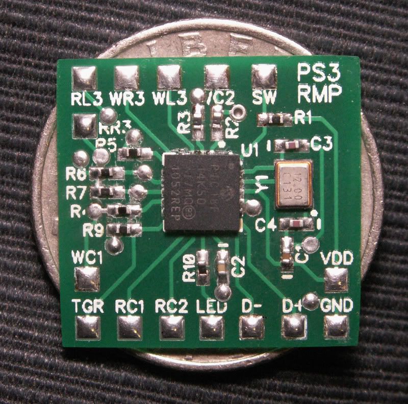
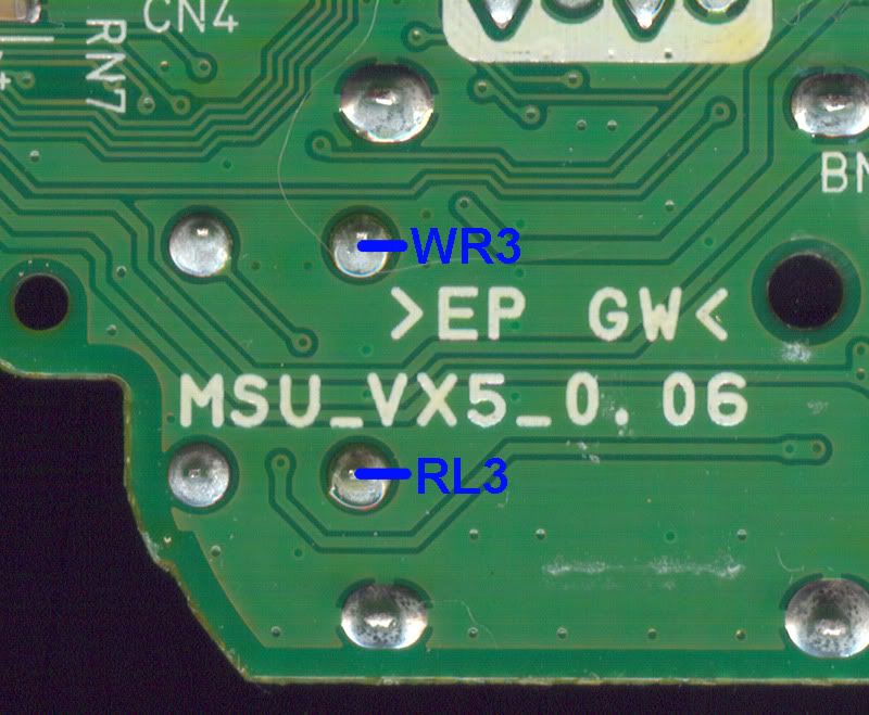
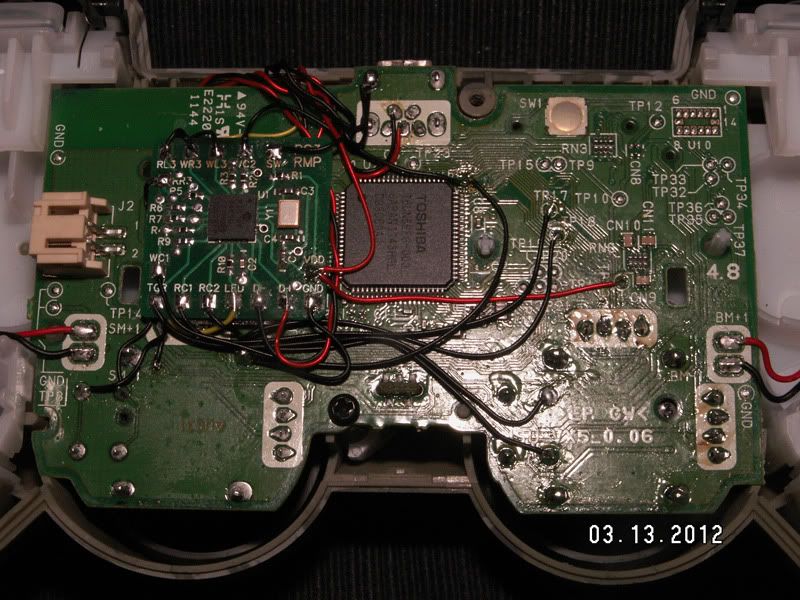
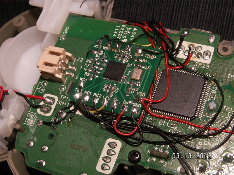
Refer to this picture and again to the pictures above to see what connections go where.
RC1 - Read COM1
RC2 - Read COM2
WC1 - Write COM1
WC2 - Write COM2
RL3 - Read L3
RR3 - Read R3
WL3 - Write L3
WR3 - Write R3
TGR - Trigger
SW - Switch (Programming button)
VDD - 2.8v power, TP13
GND - Ground
INSTALLED (the way I did it)
TESTING
Make sure you're using a battery that is either close to or fully charged and turn the controller on, the LED you installed should be Red. Tap the Programming button to make sure the PIC is working. It should change back and forth from Red / not pressed to Green / pressed. If it does not, go back and check all of the wiring and trace cuts as everything has to be connected up properly before things will work.
PROGRAMMING MODE
Press and hold the Programming button for a couple of seconds, the LED will be Green and then turn Red briefly. Quickly release the Programming button while it's Red. If you wait too long the LED will go back to Green and you have to release the Programming button and try again.
If you release the Programming button correctly, the LED will stay Red and NOT change color to Green when tapped. This means it is now in Programming Mode.
If you used the USB connector and DPDT switch, flip the switch over to the Remap chip side and plug up your USB cable to the controller and the PC. The LED will quickly flash Red/Green while it's syncing to the PC, then it will slowly blink Green when it's complete. You can now start the Remap Utility.
REMAPPING
Press the 'Connect' button (top left corner) and the 'Save to Controller' button (top right corner) should become active.
ISSUES (just in case)
This is the only problem I had after the install, so anything other than this will be a new one.
I had an issue on this VX5 after installing the Remap board. If the controller seems like all of the buttons are pressed at the same time and is unresponsive, press and hold the Programming button and see if the Sticks will then work. If it does, then the 13k Resistors need to be changed to the 14k ones and it should start working then.