A2D InstallIntroduction A2D is the first dual nub for psp EVER created. It was created by Cyberpyrot of Acidmods.
Its older than the Razor X which can be purchased from coolmods.co.uk but its still a great part in
Acidmods and Modding History.
Parts Needed --PSP Phat
--A2D Board (Has to be homemade we dont sell anymore)
--Rotary tool with cutting attachment
--PSP Phat Official Sony analog Nub
Tools Needed --Soldering Iron.
--Solder (60/40 is most common)
--Rosin Flux.
Average Time To Complete- About 1.5 to 2 hours
Difficulty Rating-4/5
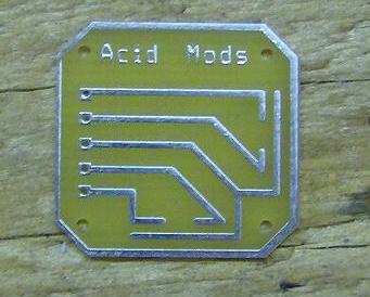
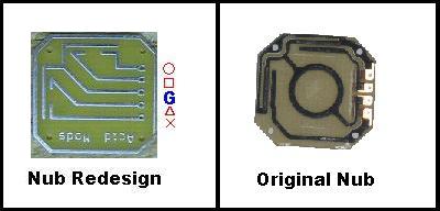
Step By Step Tutorial-A2D Board Assembly Congratulations on purchasing What may be one of the greatest mods for the psp. Here it is in all its glory but this board can be used for not only the PSP but the Nintendo DS or any other console where you want the analog feel from a digital controle. This tutorial will instruct you on the assembly of you new digital board. You will need to buy a sony stock analogstick remove the board that comes with it and replace it with the one you purchased from AcidMods. but there a few thing you must do first to the replacement board..
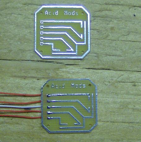
Solder five wires to the board as shown. Make sure you keep the solder points very low so as the assembly closes completely..
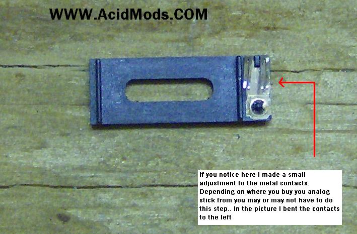
In some cases you may need to bend the contact depending on where you get your analog nub from.
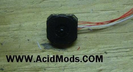
At this point it is time to take apast and reassemble the new nub here is a video showing how to take apart the nub made by califrag ------->
Nub Assembly<------

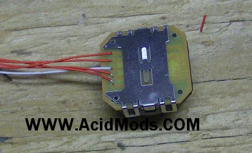
Once all together this is what you new digital nub should look like from the bottom view.
This is what you new digital nub should look like from the Top view. Now you ready to install into your console please Scroll down for the tutorial on installing in whatever console you choose..
 Testing The Nub
Once you have your nub assembled you might want to test the contacts to see if any adjustments are required.. There are two ways to test the nub 1: With the use of a continuity tester place on probe on the white center wire and the other probe on one of the red wire now move the joystick in that direction you should get a signal if not you need to make an adjustment to the contact for that direction. 2: Use a pre wired led connect one wire to a + lead on a battery connect the - to the white center wire of the board to the other wire on the led connect the red wire to the negative lead on battery now move the joystick in the direction the led should light up if not you need to make an adjustment to the contact for that direction..

If you need to adjust the contacts simply take the nub back apart and slightly bend the contact for the direction you having problems with..
 PSP Install
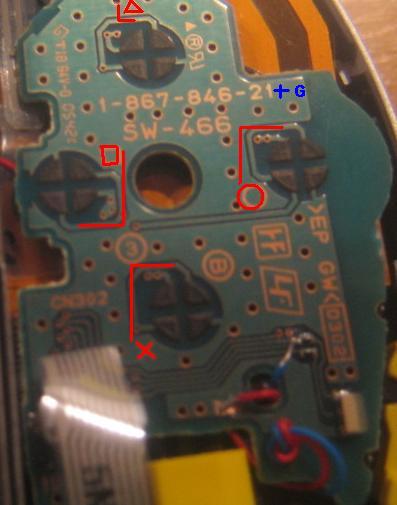
In the picture you will have to solder a wire to each of the points then connect them to the corosponding points on the NUB shown in picture 2...We are in the process of designing a raised Left and right Nub that fits in the Face Plate..
Here are the corresponding solder points.
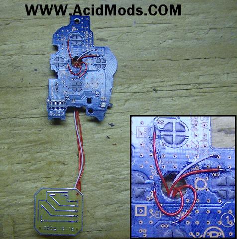
Your board should look like this on once soldered.
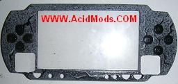
 Cutting the Faceplate
You will need to cut your face plate here.
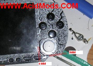
Here is a picture of the face plate cut we cut another hole in the other side to raise the other nub a little for a balanced feel
Note: I dint write this tutorial i just posted for your viewing pleasure


