PSP Hold Switch Activated LED's
IntroductionIn this tutorial I will teach you how to put hold switch activated leds in the triggers of your psp.
Parts Needed Tools Needed - Solder Iron
- scapel (or some sharp blade)
- hot glue gun
Difficulty rating: 2/5
Average Time to Complete: 10-30mins
Notes: Clean and tidy placement of your wires and leds is essential.
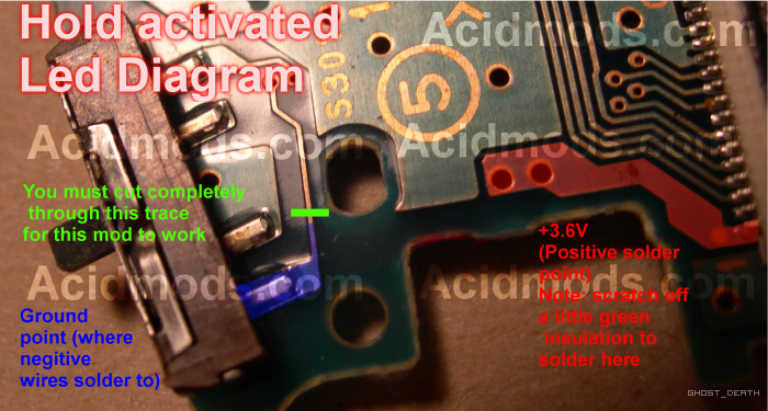
Step By Step Tutorial1- remove your psp powerboard Cut the trace shown in green using the scapel (cut right through the copper). Take note of the positive and negitive points you need to solder to.
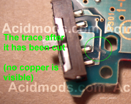
2- Heres what the trace should look like when its cut
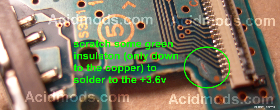
3- scratch some insulation off the positive spot on the power board, just so it reveals the copper no more.
4- Tin the bare copper you just revealed with a drop of solder, and solder a wire to there and to the hold pin on the power switch
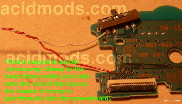
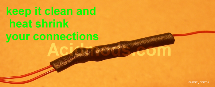
5- add your resistor to the end of the negitive wire and solder all your leds negitives to the resistor and positives to the positive wire from the powerboard. Heat shrink all your joints to keep in clean and safe.
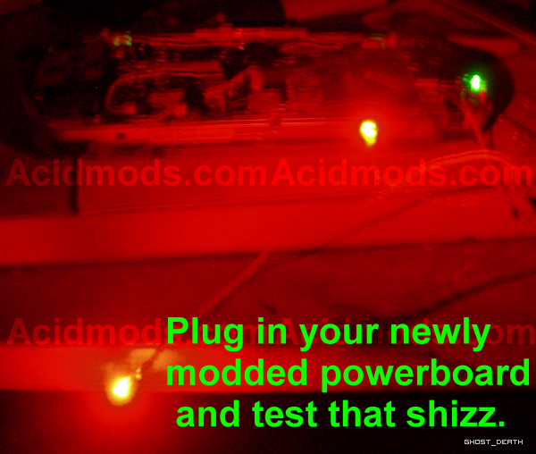
6- now plug in your powerboard, and your battery turn on the psp put on hold and test that shiz.
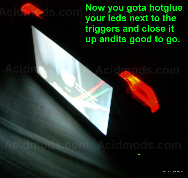
7- Unplug your battery. Rought your wires unobtrusively and hot glue your leds next to the triggers. Close up your psp and your all good.
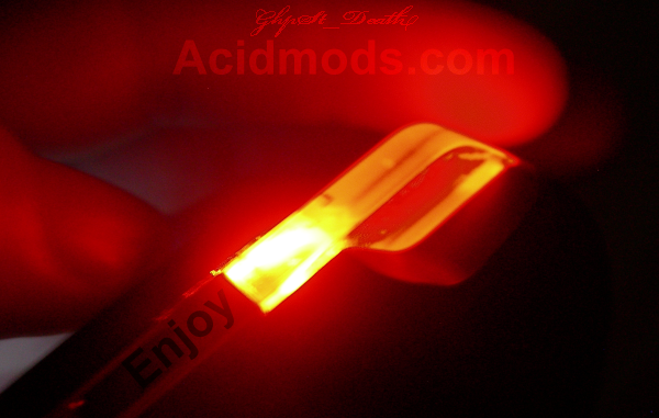
8- Show off your psp to all your mates. Enjoy.
 FAQ/ Troubleshooting
- soldered leds backwards
- wrong size resistor
- bad solder joints
That is all
GhoSt


