Author Topic: PSP GO Teardown Tutorial  (Read 9386 times)

Offline Modded Matt

  • Site Owner
  • Administrator
  • Around the block
  • *
  • Posts: 4649
  • Post quality +65/-3
  • Gender: Male
PSP GO Teardown Tutorial
« on: January 18, 2010, 07:58:19 PM »
PSP GO Teardown


Introduction
In this tutorial I will guide you through the nerve wrecking process of tearing down the PSP go. Once completed you will be able to swap or add led’s, along with other mods depending on your imagination.


tools needed
  • protective cloth (we don’t want to scratch the finish)
  • #0 Philips screwdriver
  • a small flat head screw driver or pic
  • patience


Difficulty rating: 2.5/5


Average Time to Complete: 45 mins-1 hour


Notes:
Click Picture to open full image

There are small little plastic clips holding the back plate and top cover on, use care here.

The connectors for the head phone jack, start/back button, and home button ribbon connectors have no moving parts and are very fragile. the ribbon cable is just pushed into the slot. take lots of care with this step. there is no metal reinforcing chassis like there was with the other psp's. this makes this unit even more fragile then the original models.

 
Step By Step Tutorial
1- start with a clear table, layout two micro fiber cloths or such to protect the parts as they are removed, use one for a work space and one to layout the dismantled parts.


2- turn psp upside down to remove the 4 screws from the back plate.


3- stand the psp on edge to remove the two screws from the volume bar


4- lay the psp back down lift the back plate insert flat head screwdriver between the silver trim and the back plate and pop it loose. then pull the plate down and off to free the top.


5- next we need to remove the bottom piece of silver trim. to do this start at the left side and pry the clip loose as shown and peel it towards the headphone jack


6- remove  two black screws holding down the nub and the headphone jack. lift the connector and remove the nub.


7- be careful with this step, there are no moving parts, the ribbon cables for the head phones, volume bar, and start/select buttons just pull straight out of the connector, and will just be pushed in during reassembly. remove all three.
« Last Edit: June 28, 2010, 05:12:46 PM by laxboy »

Offline Modded Matt

  • Site Owner
  • Administrator
  • Around the block
  • *
  • Posts: 4649
  • Post quality +65/-3
  • Gender: Male
Re: PSP GO Teardown Tutorial
« Reply #1 on: January 18, 2010, 07:59:03 PM »
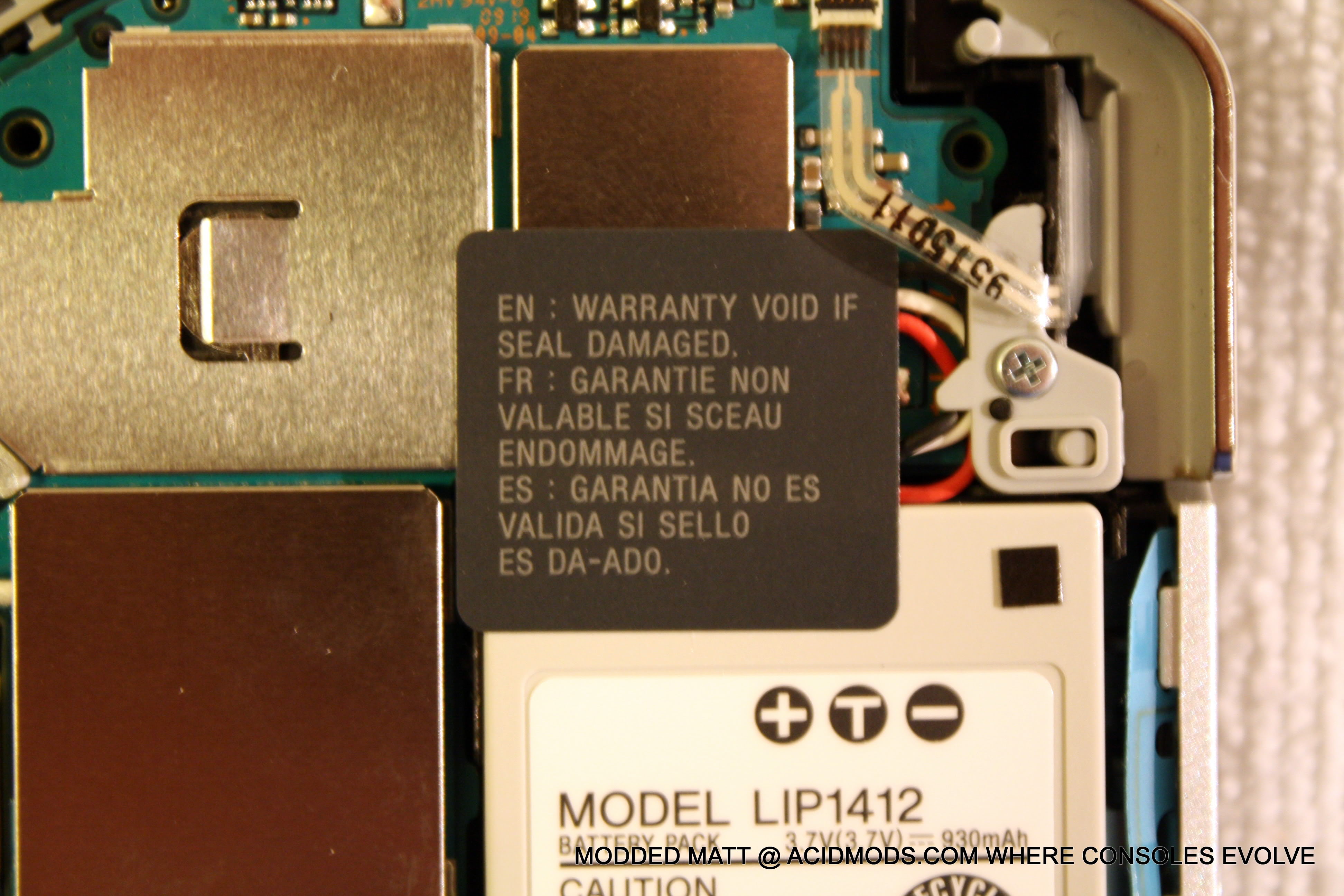
8- remove the warranty sicker from the battery.


9- remove the ribbon cables for the triggers at the standard ziff connector by lifting the black clasp.


10-remover the silver screw at each trigger and lift the trigger out, the triggers have a retainer the comes off with them.


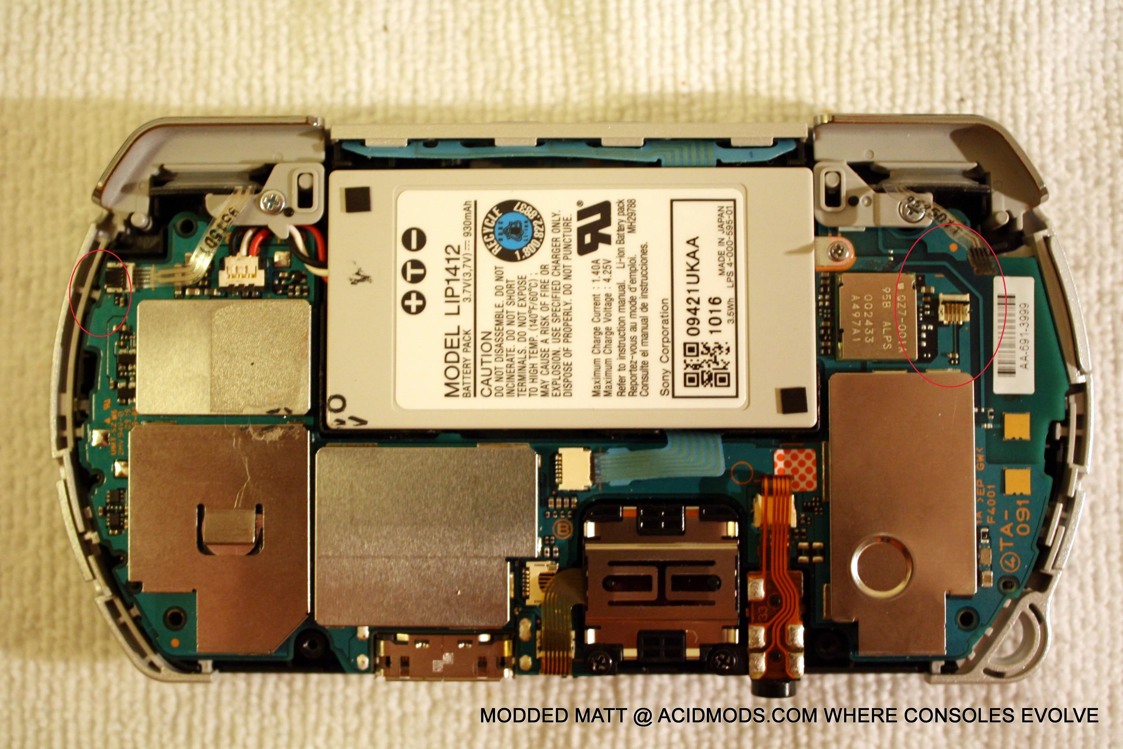
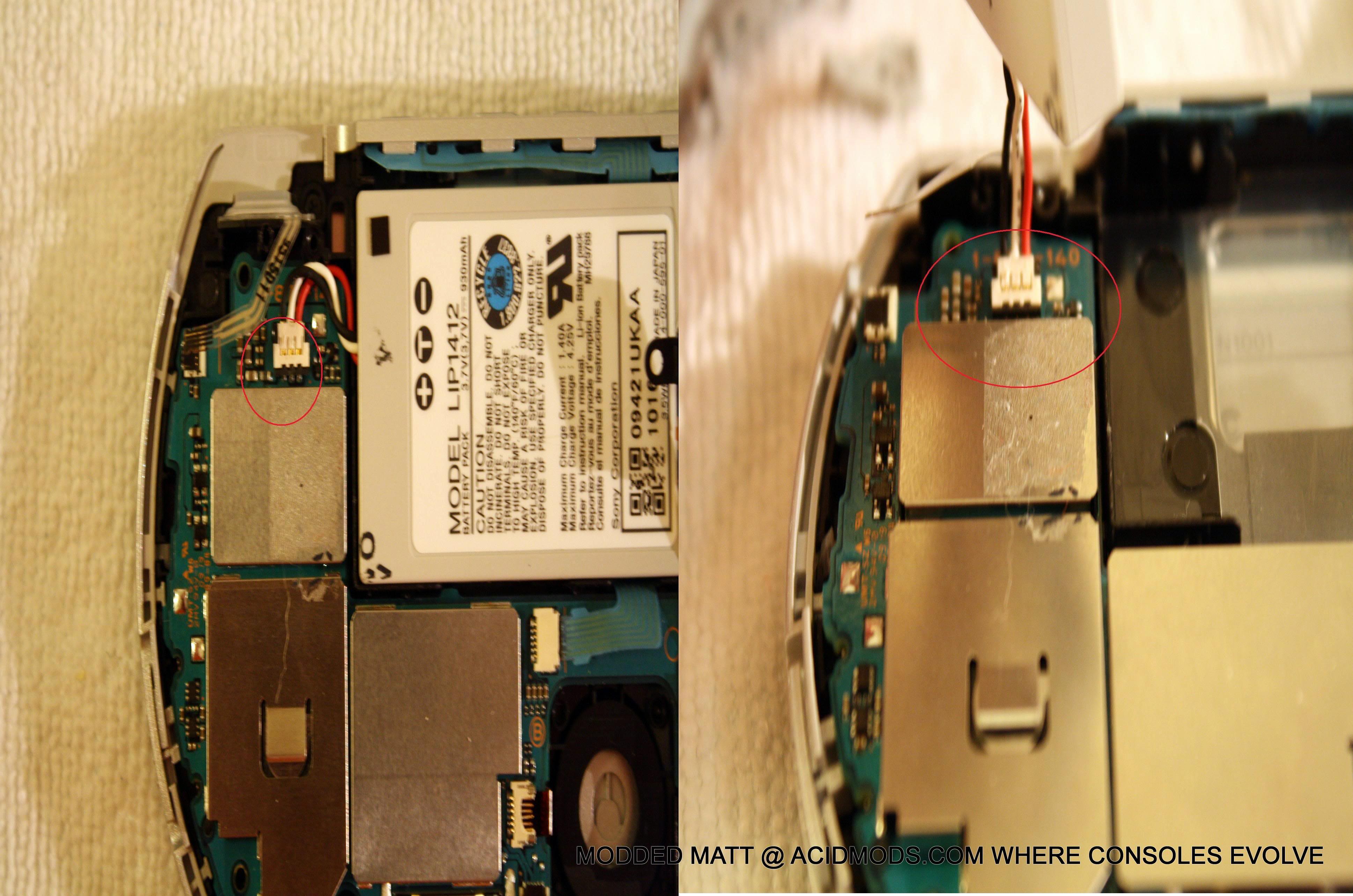
11- with the trigger ribbon cables out of the way you can now lift the battery out of the shell. the battery connector is just pressed down onto the power terminals gently lift the connector to separate it from the mobo pins.


12- now that everything is disconnected from the back of the mobo, we need to pop it loose from the plastic shell (there is still one connector left, in the center of the underside, so be careful) a good spot to pry it loose is at the right  trigger, insert pick and it it should pop free. 


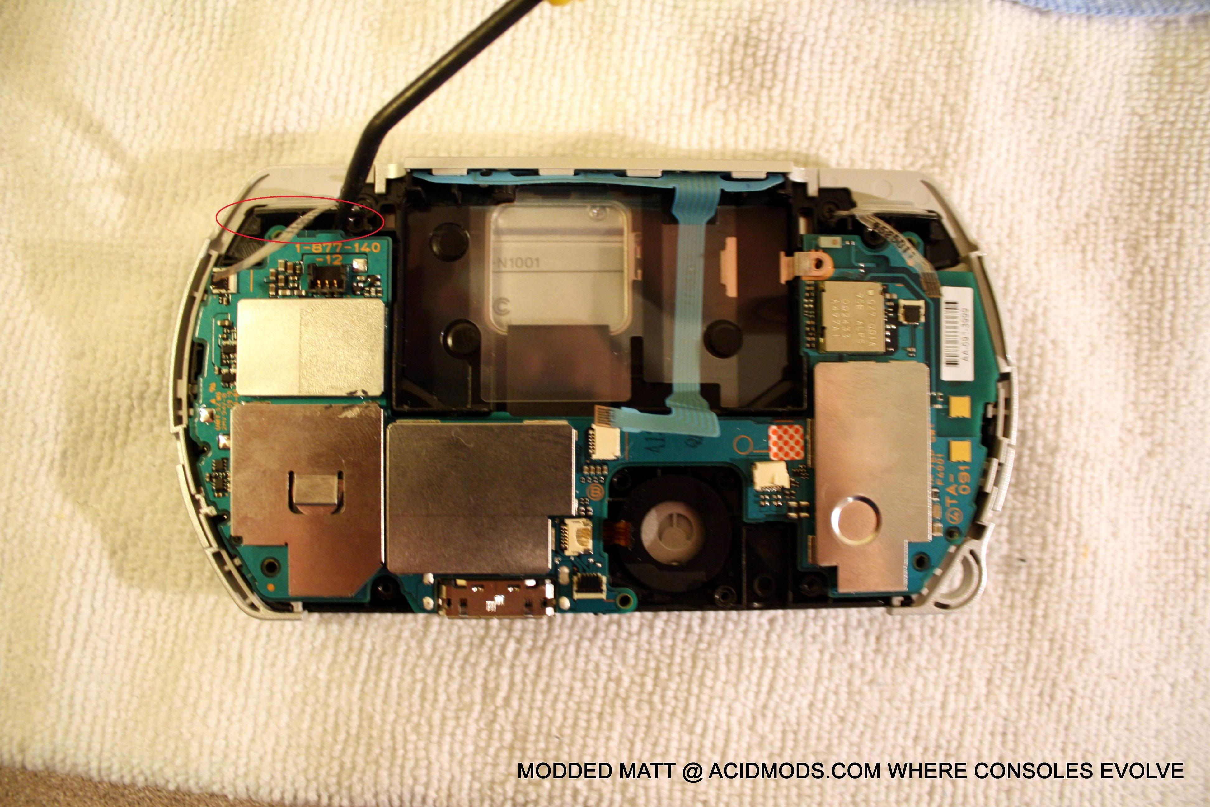
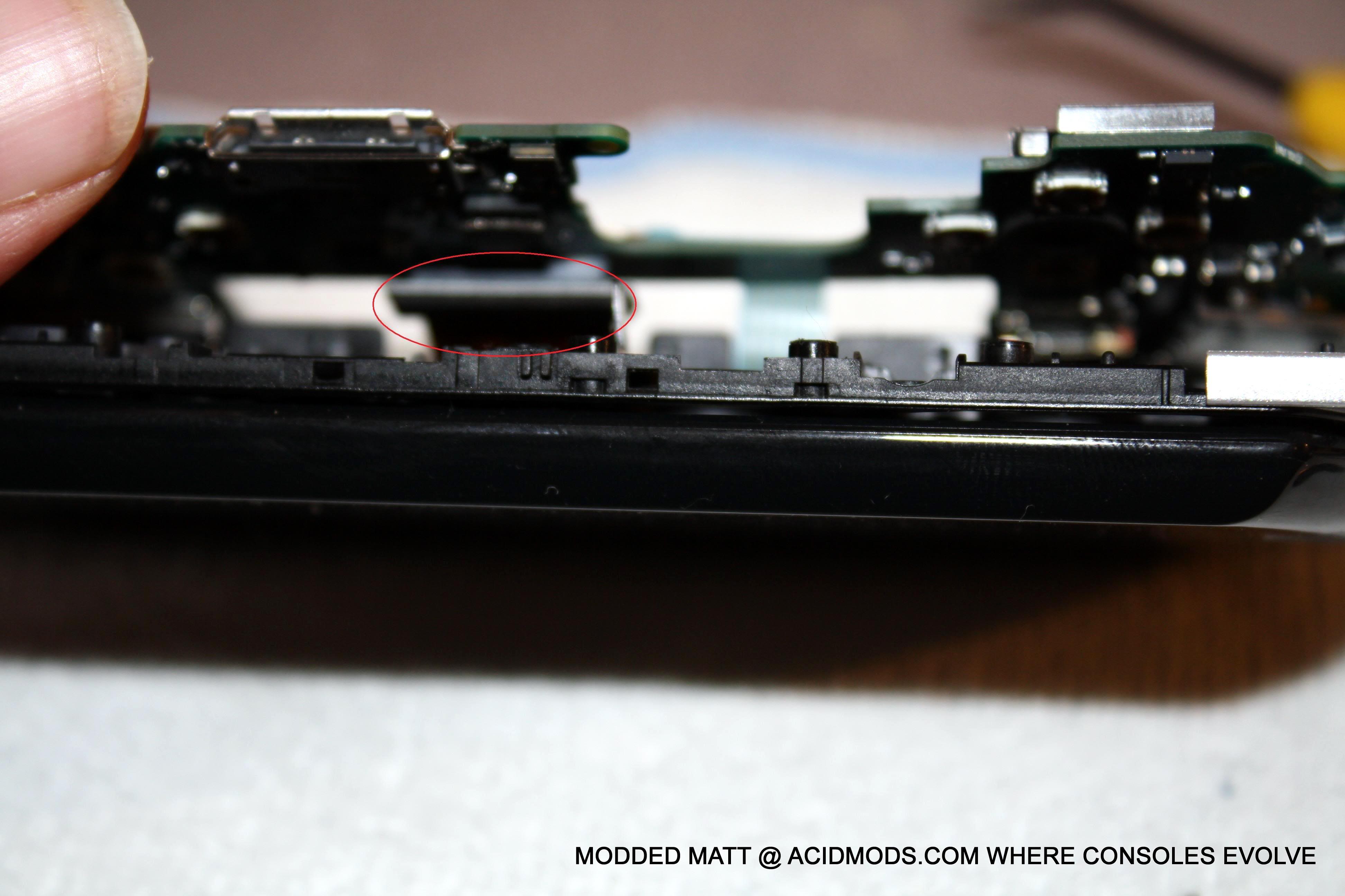
13- now stand the psp up on its edge, using your pic or small screwdriver reach in and pop the connector loose (its just pressed in) now the mobo is free.


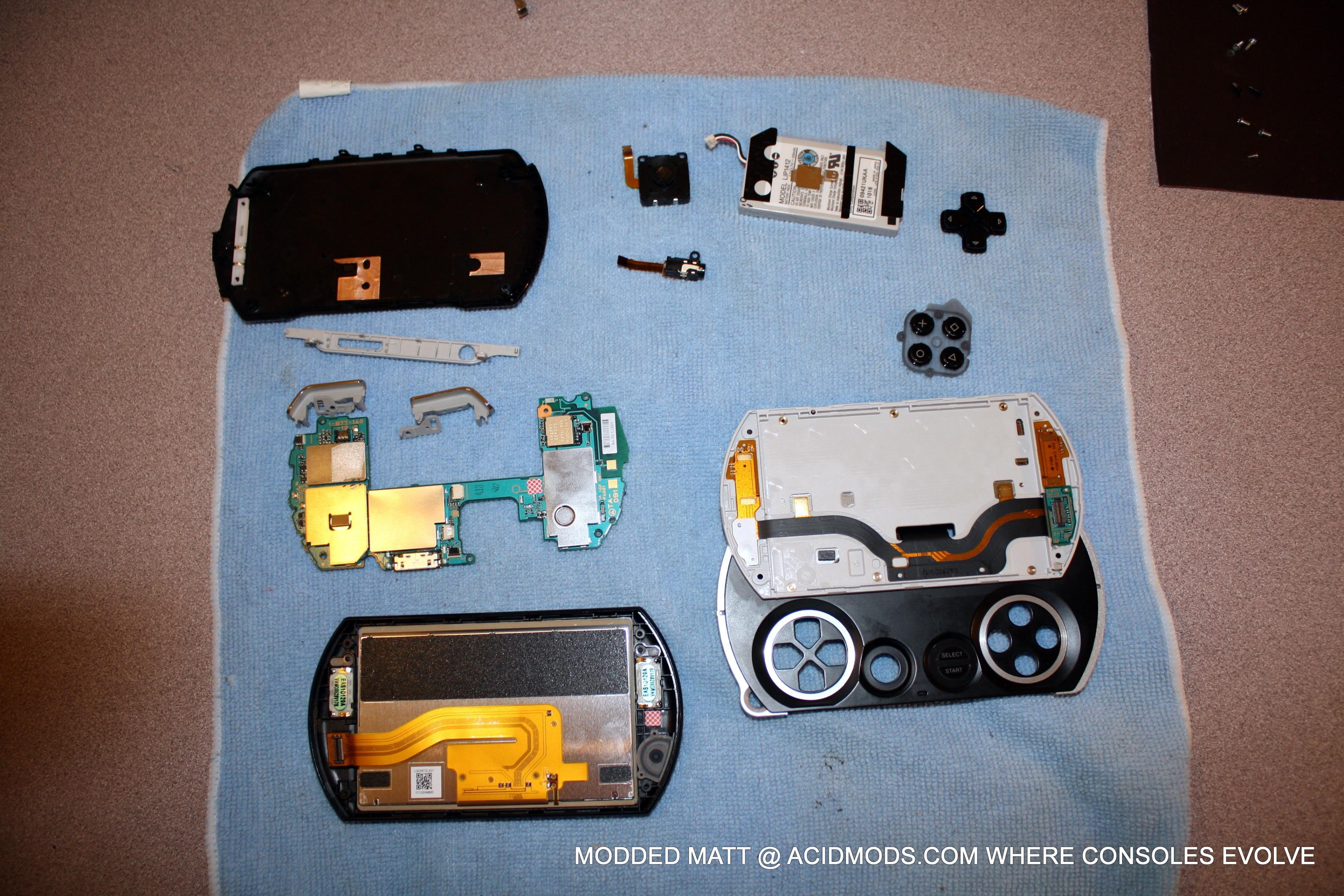
14- now that the mobo is out of the way, you can remove the other loose parts such as button pads and metal and plastic  retainers


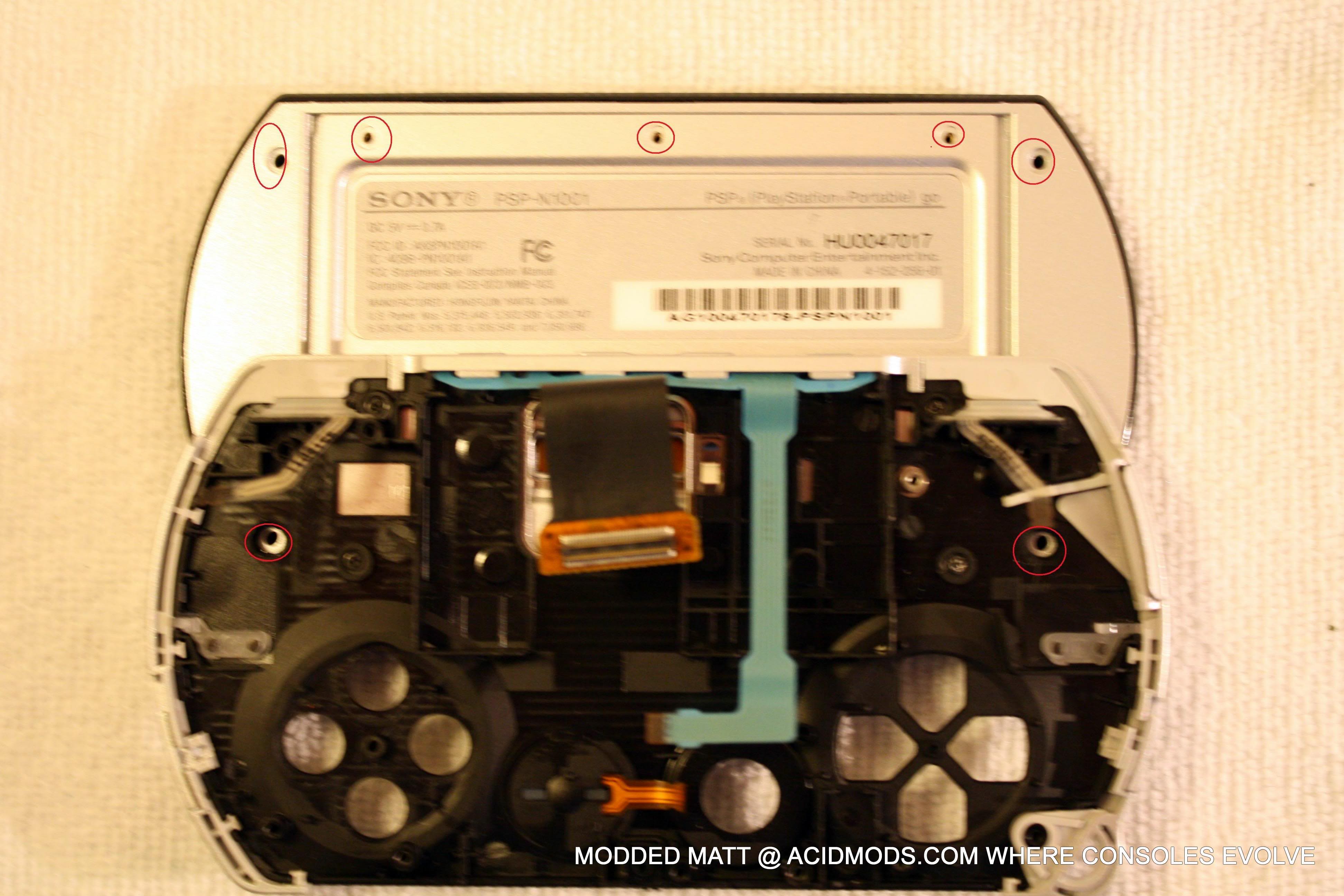
15-now remove the seven silver screws holding the screen housing together. (leave the four black screws in place they are part of the sliding mechanism and there is no reason to disturb it.


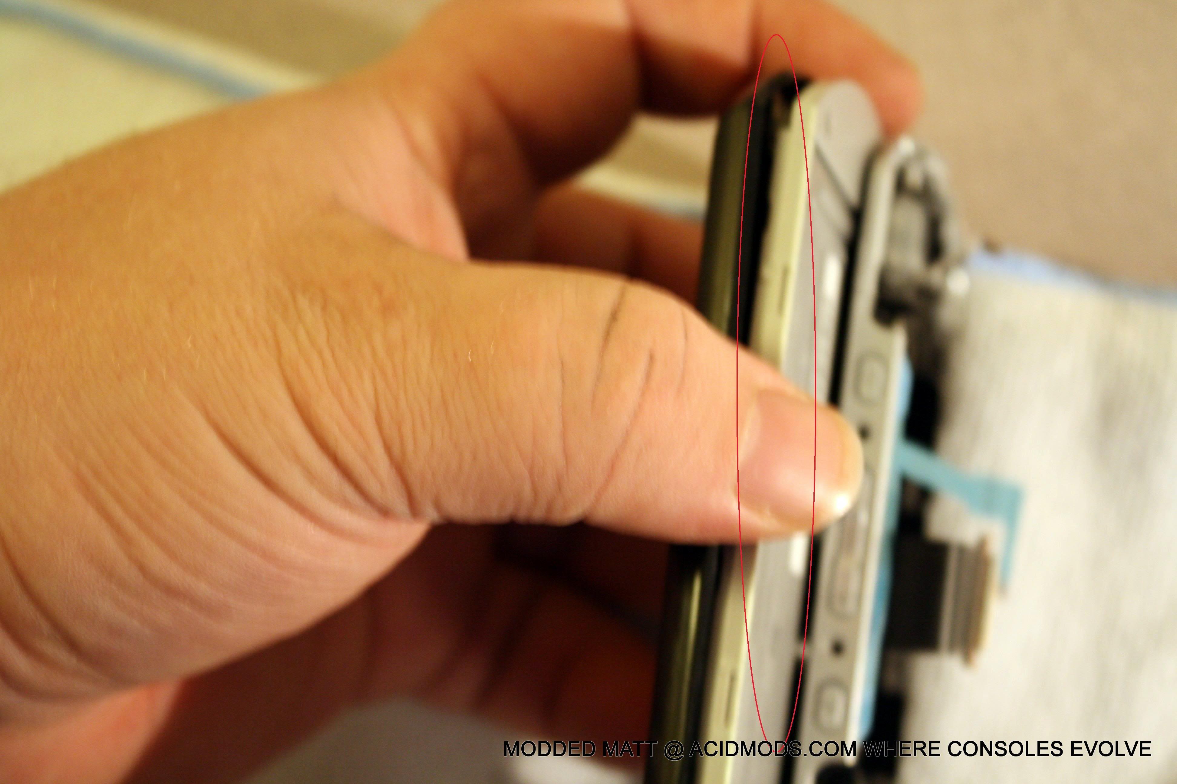
16- there are two parts to the lcd shell, a upper and lower, gently pry the two apart working all the way around the shell.


17- once it pops free you can see the LCD screen connector, reach in again with your pick and pry this connector loose (again there are no moving parts its just pressed in.


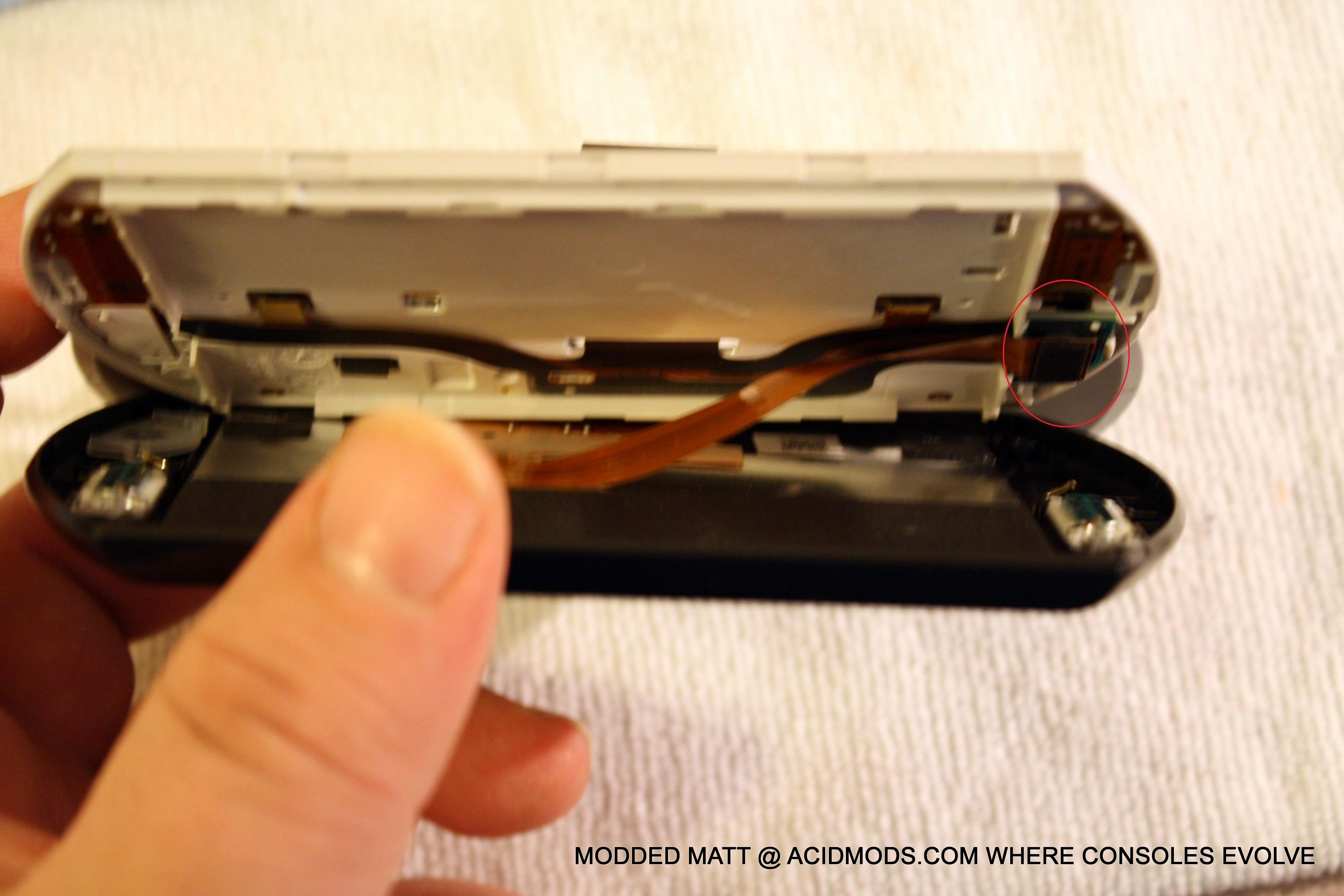
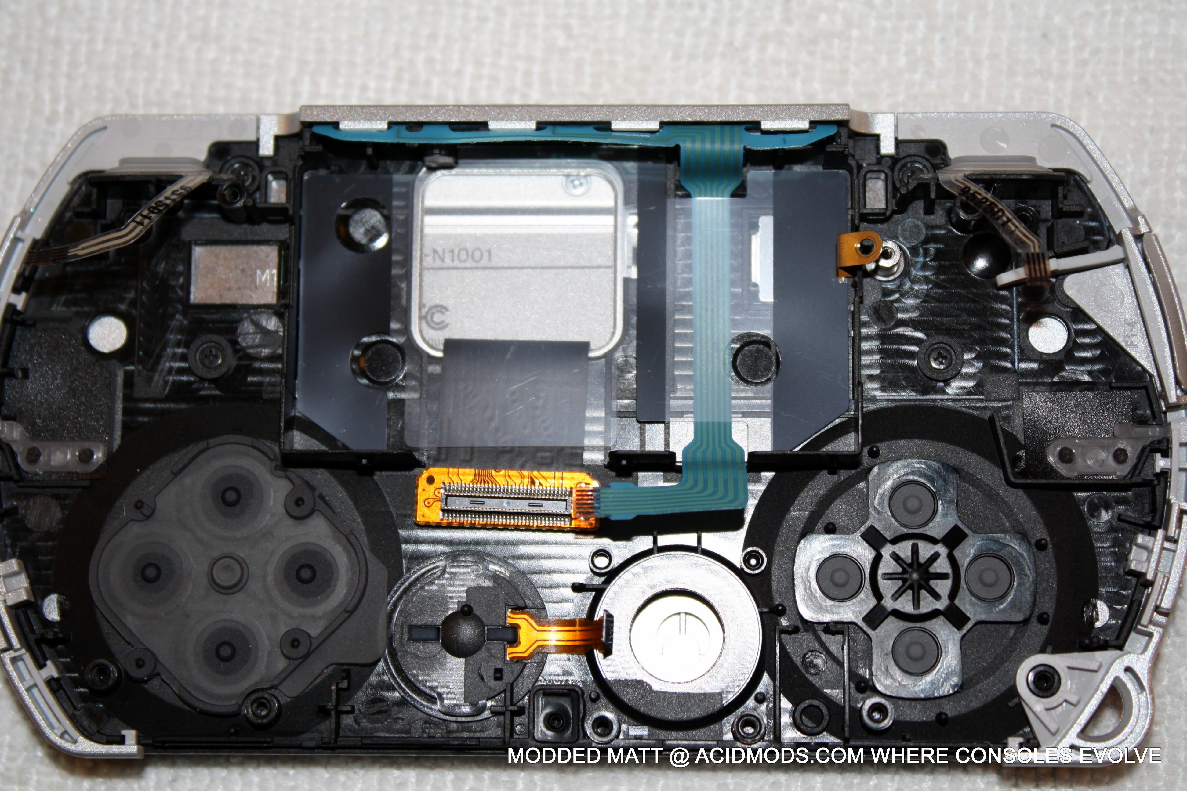
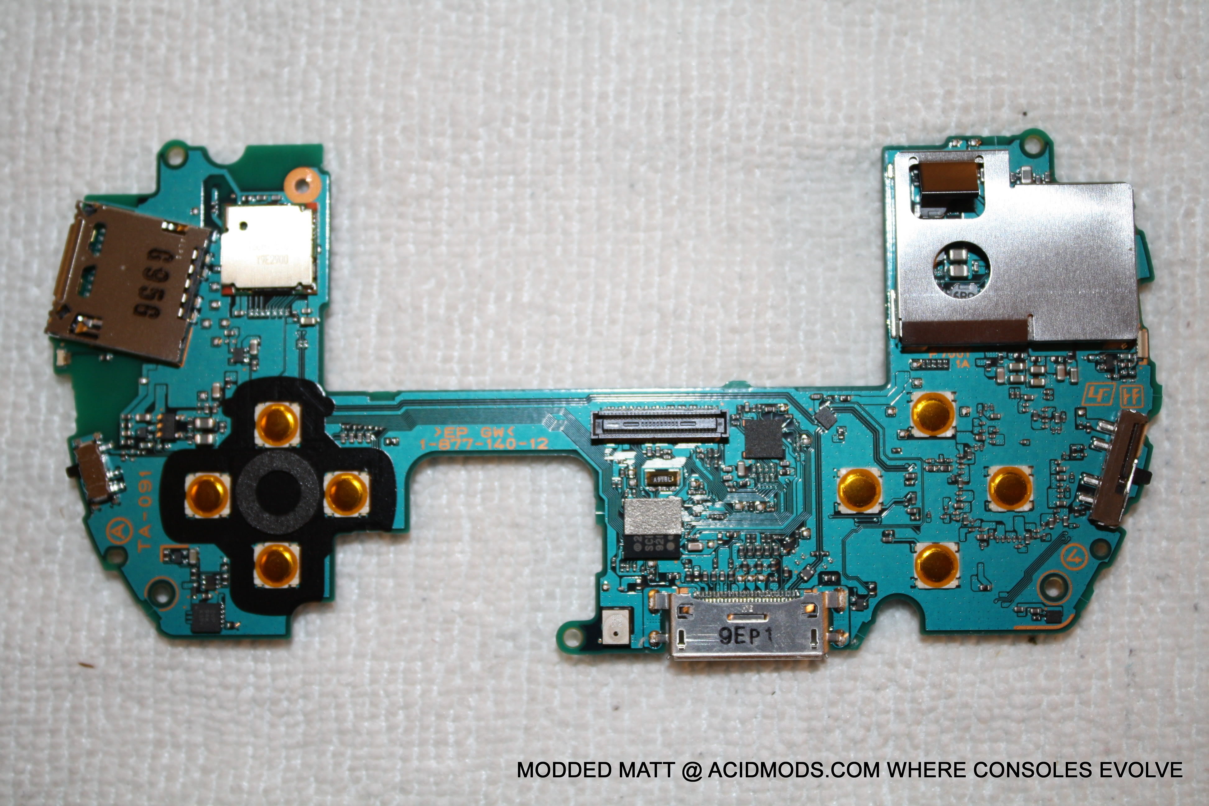
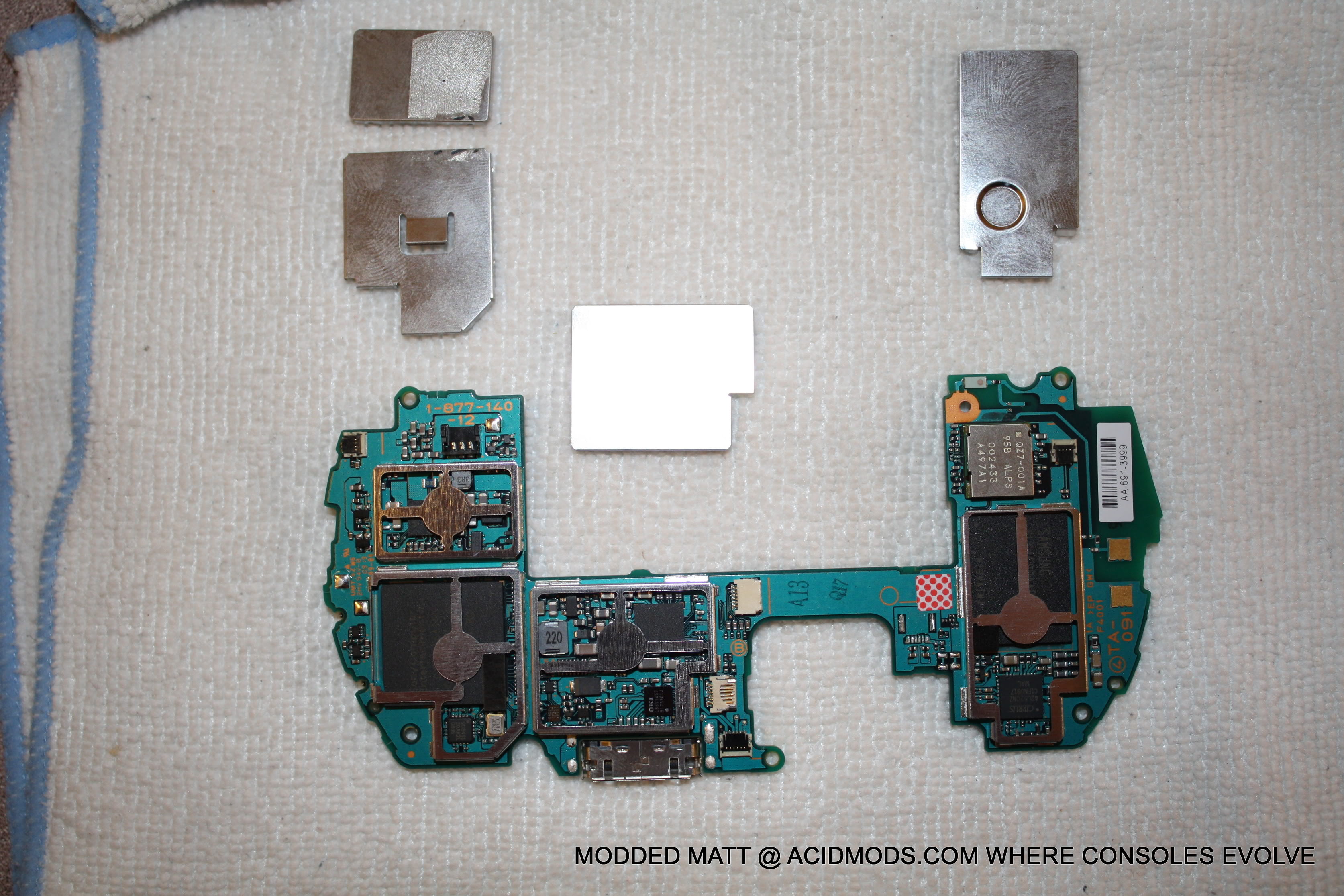
18- once the connector is removed, the LCD shell is free, which completes the disassembly. here you can see the speakers in in green. I have also included some close up pictures of the mobo for reference.


FAQ/ Troubleshooting
  • dont pry on the three connectors in step 8 just PULL THE RIBBON
  • the go will not operate when the case is not securely closed


« Last Edit: June 28, 2010, 05:16:53 PM by laxboy »


SMF spam blocked by CleanTalk
SimplePortal 2.3.5 © 2008-2012, SimplePortal