Legend:
Purple - resistance Yellow - power/Wattage
Green - current/Amps
Red - Voltage
Ohm's Law is the fundamental formula for electronics'
Voltage,
current,
resistance, and
power.
Voltage is expressed as the letter
V or
E Voltage's technical name is called
electromotive force or EMF
current or
Amps is expressed as the letter
I or
Aresistance is expresses as the letter
R resistance's technical name is opposition to electron flow.
power or
Watts is expressed as the letter
W or
Pcurrent is normally called
Amps.power is also normally called
Watts.
All of The Ohm's Law Formulas are:
To Find current-- Voltage Divided By
resistance:
I = V / R power Divided By
Voltage:
I= P / V Square Root of
power Divided By
resistance:
I = √(P / R)Electric current is the flow of an electric charge.
To Find VOLTAGE -- power Divided By
current:
V = P / I resistance times
current:
V = R * I Square Root of
power times
resistance:
V = √(P * R)
To Find POWER -- Voltage Times
current:
P = V * I Voltage Squared Divided by
resistance:
P = V2 / R resistance Times
current Squared:
P = R * I2
To Find RESISTANCE -- Voltage Divided By
current:
R = V / I Voltage Squared Divided by
power:
R = V2 / P power Divided by
current Squared:
R = P / I2
BEGINNER'S PRACTICE: | #1 GIVEN:
Resistance = 274 Ohms
Voltage = 14.5 Volts
Find my CURRENT and POWER. |
 | #2 GIVEN:
Resistance = 8560 Ohms (8.560K Ohms)
Voltage = 5 Volts
Find my CURRENT and POWER. |
 | #3 GIVEN:
Resistance = 1.2K Ohms (or 1200 Ohms)
Voltage = 12 Volts
Find my CURRENT and POWER. |
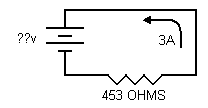 | #4 GIVEN:
Resistance = 453 Ohms
Current = 3 Amps
Find my VOLTAGE. |
 | #5 GIVEN:
Resistance = 6.7K Ohms
Power = 37 Watts
Find my CURRENT and VOLTAGE. |
 | #6 GIVEN:
Power = 1.3 Watts
Current = 400mA (or 0.4 Amps)
Find my VOLTAGE. |
BEGINNER'S PRACTICE ANSWERS:
1.] [spoiler]

(Voltage=14.5 VOLTS) (Resistance=274 OHMS) (Current=) (Power=)[/spoiler]
2.] [spoiler]
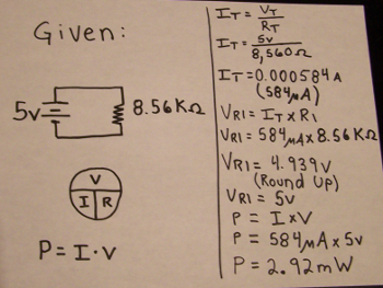
(Voltage=) (Resistance=8560 OHMS) (Current=) (Power=)[/spoiler]
3.] [spoiler]

(Voltage=12 Volts) (Resistance=1200 Ohms) (Current=) (Power=)[/spoiler]
4.] [spoiler]

(Voltage=) (Resistance=453 Ohms) (Current=3 Amps)[/spoiler]
5.] [spoiler]

(Voltage=) (Resistance=6700 Ohms) (Current=) (Power=37 Watts)[/spoiler]
6.] [spoiler]

(Voltage=) (Current=0.4 Amps) (Power=1.3 Watts)[/spoiler]
NOVICE PRACTICE:Table went here.
NOVICE ANSWERS:
1.] [spoiler]asdf[/spoiler]
2.] [spoiler]asdf[/spoiler]
3.] [spoiler]asdf[/spoiler]
4.] [spoiler]asdfa[/spoiler]
5.] [spoiler]asdf[/spoiler]
6.] [spoiler]asdf[/spoiler]
ADVANCED PRACTICE:| asdf | asdf |
| asdf | asdf |
| asdf | asdf |
| asdf | asdf |
| asdf | asdf |
| asdf | asdf |
ADVANCED ANSWERS:
1.] [spoiler]asdf[/spoiler]
2.] [spoiler]asdf[/spoiler]
3.] [spoiler]asdf[/spoiler]
4.] [spoiler]asfd[/spoiler]
5.] [spoiler]asdf[/spoiler]
6.] [spoiler]asdf[/spoiler]


