Similarities and differencesPCB: PCB design rules are well known.There are minimum hole sizes, minimum trace width,
minimum space between traces and pads. We know to keep copper geometries a certain distance away
from the routed edges. We know about hole size and outline tolerances, copper and board thicknesses
Flex: Flex circuit design rules are very similar! We must pay attention to all of the same issues,
minimum hole sizes, minimum trace/space specifications, distance to edge and tolerances.
Traditional PCBs and flex are fabricated in much the same way for the first several steps. The flex material,
typically copper clad polyimide, is allocated,drilled, plated, imaged, developed and etched just as printed circuit boards are.
The next step however is where the changes occur. The panels must be baked as are PCBs to remove moisture from the wet
processes, then however where a PCB would go to a solder mask station, flex circuits go to a cover layer
station.
The insulating layer of a flex circuit is made of polyimide the majority of the time. This is not a
screen process as it is in PCB fabrication, it is a lamination process. Therefore the rules for oversize of
openings are a little different.
Another area we must worry about that isn’t common with PCBs is the
“flex area”. Some
reasons for using flexible circuits are simply size and weight, but many of the applications take
advantage of the flexibility and use the circuit in this manner. There are two typical ways this is done.
Flex to fit: The circuit is flexed once only to fit into the assembly and
Dynamic flex: This circuit will not
only flex to fit into the assembly, but will be dynamic during operation. Either scenario requires a bit of
thought be put into the trace routing and pad placement in that area. First it’s best not to have any
components (solder pads) in this area. Whether the flex is formed once for fit or dynamic, the solder
joint still will be the weakest part of the circuit. Solder, RoHS or leaded, is rigid and not intended to
bend, flex or twist. Therefore if those joints are in the flex area you will likely see fractured solder joint
at some point. It’s best to keep all solder points at least
.100” (100 mils) away from flex areas. Further is
better if real estate allows.
Traces should route through the flex areas perpendicularly. This allows us to take advantage of
the malleability of the copper. Rolled annealed copper has grain and if run horizontally in the flex area,
may split or fracture leaving the engineers an intermittent issue to try to find which is very frustrating
and difficult to identify. It’s best to route traces at a
90 degree angle through the flex area and then
make the necessary direction changes to allow completed design.
The only other big change to keep in mind is that angles in flex are not preferred. So the miter
tool on your design software should be set to round instead of angular when designing a flexible circuit.
The natural flexibility affects the transition from horizontal to vertical trace routing so we like to make
that transition as seamless as possible. Rounded corners give us that luxury.
So as you can see the design tactics for Flexible Circuits don’t differ much from traditional PCBs.
All of the typical specifications still apply and we add a few more things that require special attention.
Cover layers require bigger openings than traditional solder mask, trace directions matter in the “flex
areas” and miters should be round instead of angular.
You may use all of the same CAD tools for design
and output Gerbers as you would for any PCB.
Below Are Few of Felx Board For Xbox 360 from 2008 Till 2012,
Flex is not Cheap and if you pick the righ Electronic Component Packaging type you can Assemble by hand with steady hands.
IF you Use (QFN) Packaging Like I have to save Space than Its best to have them Asssemble at Factory.
The Born of Flex Xbox 360 CG / Matrix  Cg/Matrix With Switch select
  CG / matrix Auto Select
 Final
Final  Final With light
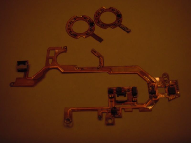
And The Big Daddy With All Adon 


