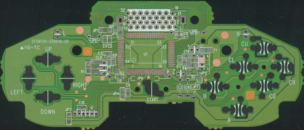
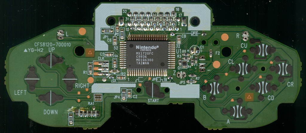
This schematic isn't what I'd consider 100% complete, as it doesn't include the Encoder Stick board, and the SMD component values aren't known right now. I could guess what most of them are, though that's not very accurate in my book. As far as what is connected to what goes though, it is accurate.
Note: This schematic also does not have the Jumpers shown, since they're just a way to get from one place to another by 'jumping' over a trace or from one part of the board to another part, so for all intents and purposes a jumper is the same as a trace, they're just not shown here is all.
200010 -
https://www.acidmods.com/RDC/NINTENDO/N64/200010.pdf700010 -
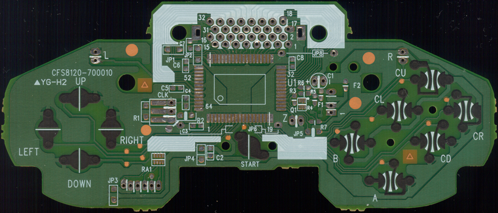
https://www.acidmods.com/RDC/NINTENDO/N64/700010.pdfTop scan of the main PCB with all components removed. (The bottom side has no components or traces, just 4 jumper wires, but those are marked on this side where they go. Also the L, R and Z button boards are simply Normally Open contacts like the rest of the buttons on the controller, so no real need to show them either)
200010 CLEAN 700010
 700010 CLEAN