Author Topic: Xbox One Controller 1708 successful repairs - pls share tips and learning curves  (Read 520 times)

Offline mummydidit

  • Guppy
  • *
  • Posts: 2
  • Post quality +0/-0
  • Gender: Female
  • Acidmods User
I've just managed to repair three of my xbox controllers in quick succession after many failed attempts. I've taught myself how to solder through hole on these poor things, they're missing pads left right and centre because I was having trouble finding concise information about how to do it and what to watch out for.

The soldering iron I used is trash, like trying to perform surgery with an axe. Used lead free solder, acidic flux, desoldering wick and no third hand. So uphill battle from the start.


Here's what got me there:

Soldering iron needs to be hot enough to melt solder within 2-3 seconds of contact
- if longer too much heat travels to the board and parts = high risk of removing pads and damaging parts, at best a poor-quality cold soldered joint

The metal pads around the holes are VERY IMPORTANT!
- it is insanely hard to solder without a pad, the solder just doesn't want to stay put
- traces connect to the pads (traces are the pathways from one component to another)

Learn what a good soldering joint looks like so you can tell if you've got too much or not enough solder
I liked these quick references:
https://www.raypcb.com/wp-content/uploads/2021/09/SMT-Through-Hole-Soldering.jpg
https://cdn.mikroe.com/blog/2016/08/solder-joints-examples.jpg

- If the pad is damaged you might be able to see a tiny bit of copper peaking out at the end of the trace, or you might be able to scratch back to the copper layer of the trace near where the pad was. Maybe you can drag solder across this to make connection but I had limited success with this.
- - I found it MUCH easier to find where the trace lead to and use a jumper wire.

I'll comment against this post with my two repairs on controllers with the left stick stuck at 100% up and a bumper repair.
« Last Edit: April 28, 2023, 04:08:51 AM by mummydidit »

Offline mummydidit

  • Guppy
  • *
  • Posts: 2
  • Post quality +0/-0
  • Gender: Female
  • Acidmods User
Xbox Controller 1708 - Right Stick module replaced, then up input of either 80%+ or 100%

Those poor pads...


I dove into learning how the potentiometers work to try to understand why these munched connections were leading to a 100% direction.

I knew one or more of the three round pins on the side were my problem, relating to the vertical up/down movement of the stick.

Looking at RDC's PCB scans, traces and info here 
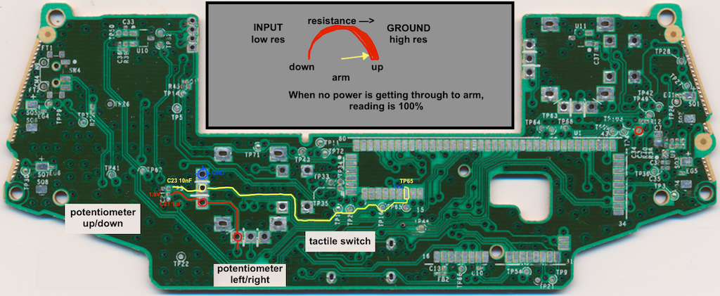
https://acidmods.com/forum/index.php/topic,43981.0.html

Top pin is the ground.
Middle pin is the wiper/arm - it moves as the stick is moved up/down. It gets a reading for the position of the stick and feeds it elsewhere on the board.
Lower pin is the input - where the power is coming from.

When the stick is pulled down the wiper rotates closer to the input. There is less resistance here so the wiper carries a higher voltage.
When the stick is pushed up the wiper rotates further from the input. There is more resistance here to the wiper carries a lower voltage.

So when there is little to no connection to the wiper there is low voltage and it interprets this as the stick being pushed far forward.


...

I tried several times to smudge the solder against the scraped traces but had no luck.


So again referring to RDC's comments I researched how to use wires to jump to the correct TPs.

I used the wires from the dual vibration motors (I always turn this off anyway, personal preference) and connected:
Top pin to another ground connection that was in decent condition.
Middle pin to TP65 over near the SOC board.
Lower pin to TP103 / the left pin of the three RX potentiometer pins along the bottom.

And she's alive!!!!


If fixing RX the left pin links to TP103, the middle pin to TP66 and the right pin is ground.

These are the grounds


SMF spam blocked by CleanTalk
SimplePortal 2.3.5 © 2008-2012, SimplePortal