Internal bluetooth TutorialIntroduction Since people have been asking for a tut, I did the best i could. Cant help with pics about ripping apart the headphones, as i did that a couple months ago and didnt take pics... sorry. Many many thanks goes out to Fufa and Budgray19 for all their help! Anyway, here's the tut:
EDIT: one other thing i forgot to mention, with the mod set up this way, you will need a dummy plug to go into your headphone jack. Fufa and I have both tried to get the jack to short through a switch, but we have come to the conclusion that it is mechanical and cant be helped.
To make a dummy plug, simply cut the end off of an old set of headphones. Plug that into your headphone jack and you are good.
Parts Needed -30 gauge kynar
-Electrical tape
-Will probably need de-soldering braid (I always do)
-Anything else you can think of that might be handy.
Tools Needed -Soldering Iron
-00# phillips
-Nice edged flathead
-Rosin core solder
-Drill with small bit
Average Time To Complete- About 1-1.5 Hour
Difficulty Rating-3/5
Step By Step Tutorial-You're going to need a set of these headphones... or similar ones... you can find them pretty cheap on ebay. They are pretty decent quality made by Logitech. I got mine for around 30
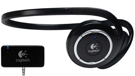
Here's a pic of the headphones after I modded. Basically, i dremeled down the headband and speaker cones until they fit together. Then I mounted the battery and wired the common and left and right speaker wires to a stereo female plug that I got from radioshack. You can rip the guts out and mount into something else if you like, but i liked the dongle idea.
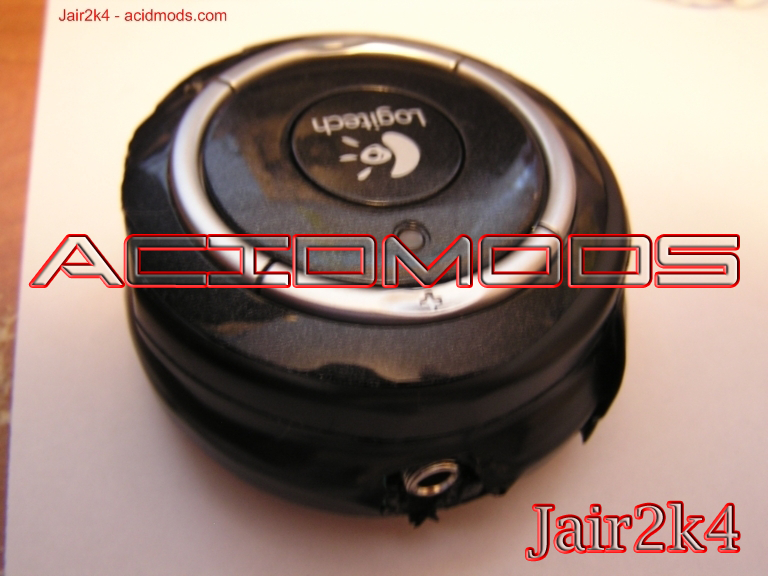
This is our BT transmitter, we are going to wire up and mount this inside the psp. To get at the transmitter, you need to use your phillips to get the transmitter housing apart. I did this some time ago so I do not have pics, however it is quite simple to do. Once inside the housing, you will see a battery on one side and the board on the other. Just unscrew the board and you are good.
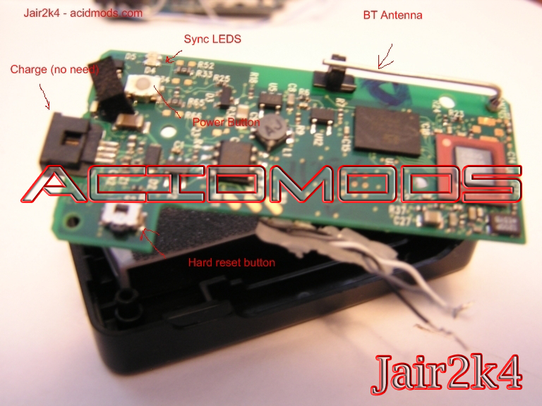
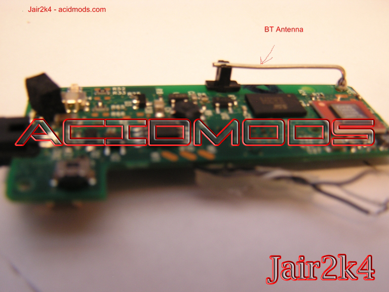
The mod itself is pretty straight forward. Solder your kynar up to these connections. we'll be stringing them through the hole we are drilling in the backplate. See the completed solder job in a few pics farther down to see where to solder the power leads. (thanks Fufa for the pic!)
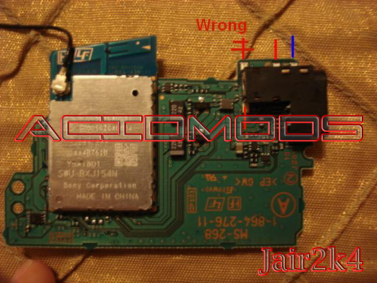
It should look like this after soldering: (DONT SOLDER ON THE DONT SOLDER AREA...) I was just testing out at that point in hopes of finding a way to ground the connection so I wouldnt have to use a dummy plug. We'll get the board put back in the psp in a couple steps
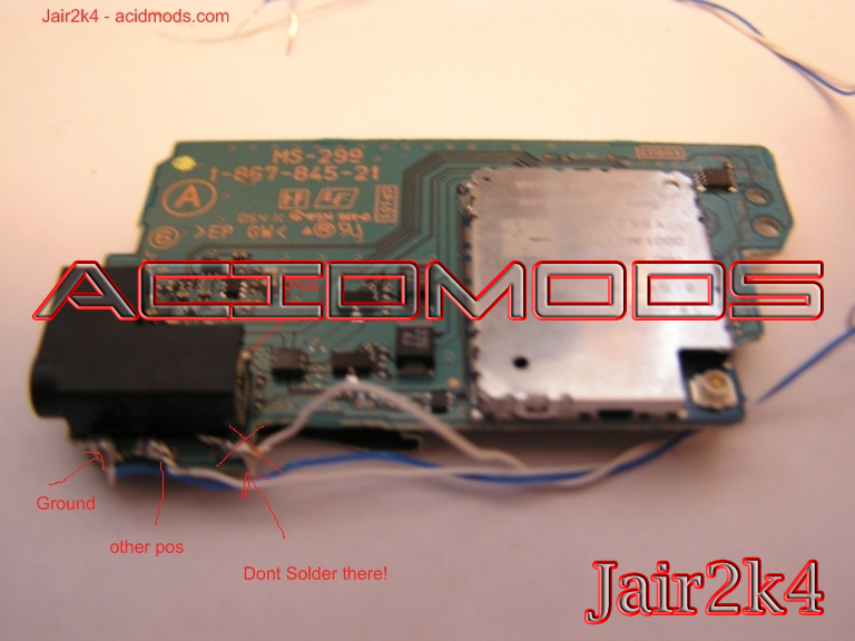
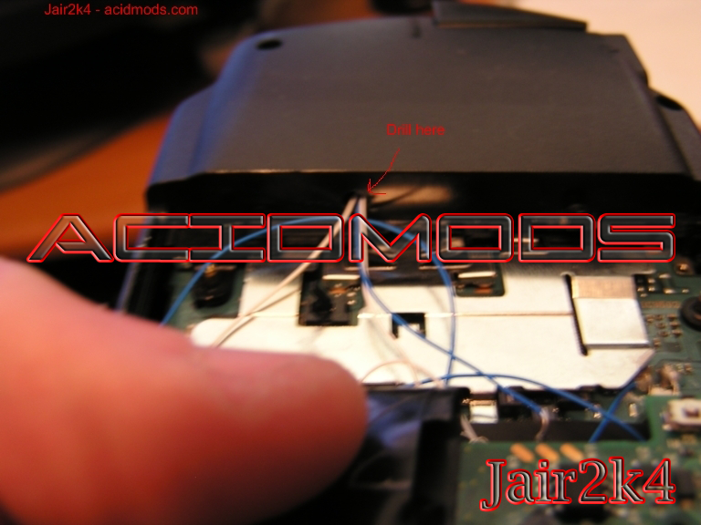
You're going to want to drill a small hole to the area where your wires will be threaded. I did mine right in the center so i would have lots of room to work with. All told we should have 5 wires coming through this hole so keep that in mind
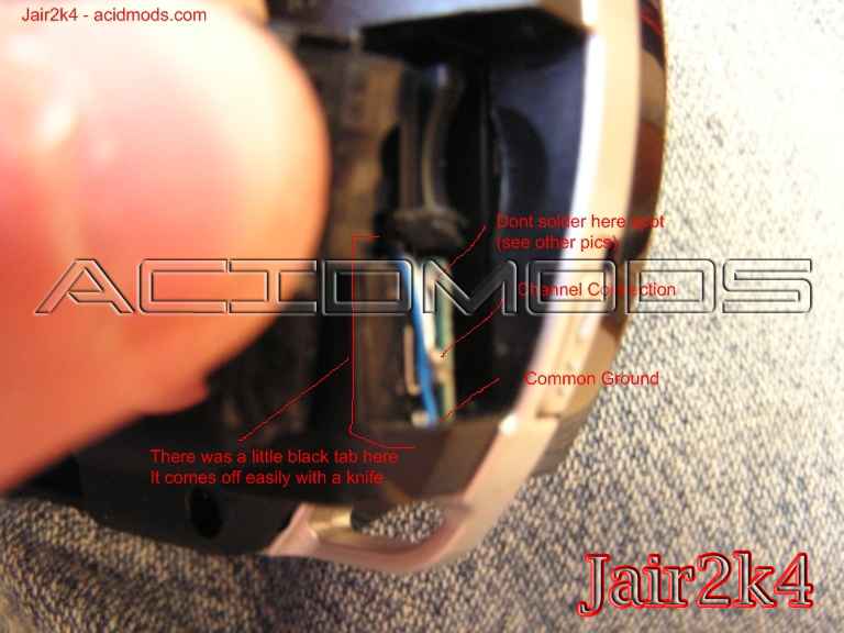
Before you mount the board back in the backplate, you have to cut off a small piece of plastic so that the modded board will fit. To do this, Use a knife to gently slice the plastic part away from the rest of the backplate. This plastic piece is the only thing keeping you from seeing your headphone jack solder points when you open your memstick door.
After that you can put most everything back together, being careful not to break any wires. I would reccomend stringing the soldered wires by the jack around to the back. When putting the board back in, you might have to help the jack slide into place by using your flathead on it through the memstick door. After all that, you should have something that looks like this
If you haven't done so already, desolder the contacts from the original stereo plug on the BT transmitter.
String your wires out to your BT transmitter, and solder them up to the same spot that the original stereo plug was connected to. these are the points you will want to solder to (MAKE SURE that you check with a multimeter, the points could potentially be different for you!
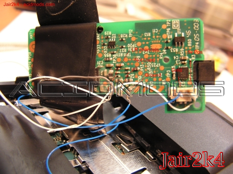
All you need to do now is hook up some power!
You can connect the BT transmitter to one of the power points on your psp, choose which one you like the most, here is a pic of where i soldered on the back of the mobo. Just make sure you check with a multi meter first!:
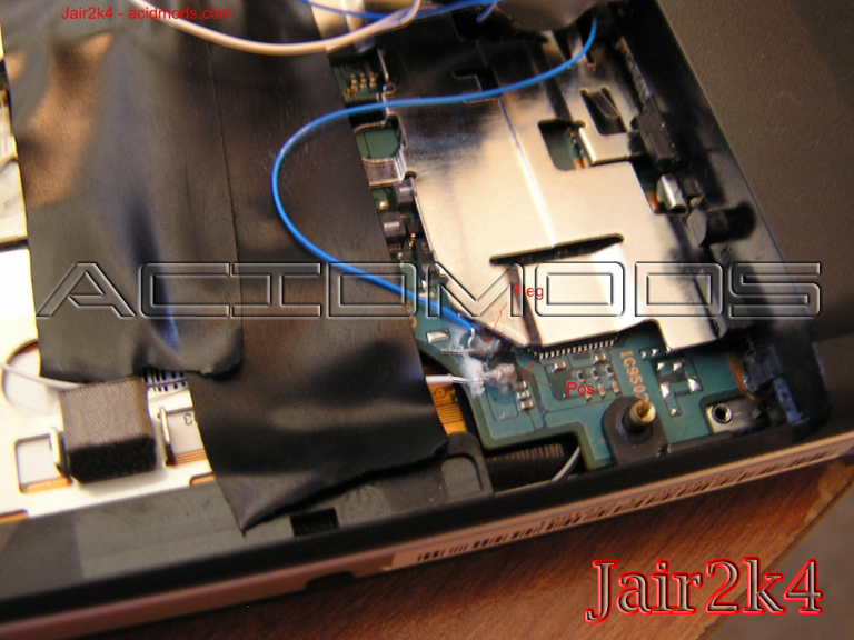
After all this, you will end up with a transmitter covered in wires. I am planning on mounting mine into my umd door so that I can press a button from the outside to turn it on. There is no wrong or right way to do this! Mount it how you think best. This is how i did mine (temporarily)
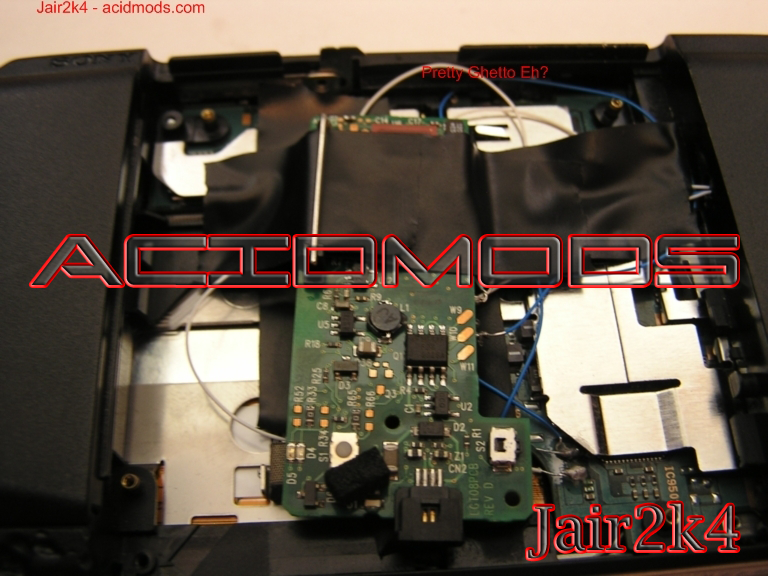
And thats all there is to it.. I know this wasnt the best tut in the world, but i hope it helps.